

Crankcase ventilation


Thread Starter
Scooby Regular
Joined: Feb 2010
Posts: 376
Likes: 0
From: Sweden
Hi.
I've been having problems with a small oil leak the since I got the engine running again. I thought it was from the oil temp sensor I have over the 3 cyl. But today I noticed one of the crankase ventilation hoses to sit a little loose. It is tight with space under the intake manifold so I took a screwdriver and tried to get it in right but then it got disconnected all together. So I took the intake manifold off and noticed that the new block got an extra port on the block. And that the hose I had connected to that port should be the one connected to the valve under the throttle body. I had it done wrong in the first place. How do I solve this the right way? Should I get a y-connector to that hose and just connect another hose down to the second port? Then the second port on the block is connected to the other one, the valve on the intake manifold and the turbo inlet hose.
The car is a v5 sti type r and the new block is a new age scdb ej207.


Or should it be connected to the hoses that runs between the heads like it is on this?


I've been having problems with a small oil leak the since I got the engine running again. I thought it was from the oil temp sensor I have over the 3 cyl. But today I noticed one of the crankase ventilation hoses to sit a little loose. It is tight with space under the intake manifold so I took a screwdriver and tried to get it in right but then it got disconnected all together. So I took the intake manifold off and noticed that the new block got an extra port on the block. And that the hose I had connected to that port should be the one connected to the valve under the throttle body. I had it done wrong in the first place. How do I solve this the right way? Should I get a y-connector to that hose and just connect another hose down to the second port? Then the second port on the block is connected to the other one, the valve on the intake manifold and the turbo inlet hose.
The car is a v5 sti type r and the new block is a new age scdb ej207.
Or should it be connected to the hoses that runs between the heads like it is on this?
Thread Starter
Scooby Regular
Joined: Feb 2010
Posts: 376
Likes: 0
From: Sweden
Is it correct that it is a extra port for avcs heads? So that I could just plug it? Or would that cause to high crankcase pressure?
Last edited by goffemannen; Jun 6, 2014 at 04:23 PM.

If you have fitted a later engine then yes it will have two crank case breathers. As long as one is correctly connected up IE comes out of crank into t piece which vents most towards PCV valve and some towards turbo inlet then it should be fine to block the other one.
A load about breathers to read here through the link on that thread.
https://www.scoobynet.com/general-te...-plumbing.html
A load about breathers to read here through the link on that thread.
https://www.scoobynet.com/general-te...-plumbing.html
Thread Starter
Scooby Regular
Joined: Feb 2010
Posts: 376
Likes: 0
From: Sweden
Okey. Yes the port closest to the turbo is going to be connected to the pcv and the turbo inlet as standard.
I found a big thread on nasoic and found this:
It should be blocked. That port has no oil separator like ALL THE REST OF THE PCV PORTS because it isn't a pcv port. In fact that port is directly above the crankshaft and massive quantities of oil gets slung up into that port. Which is the exact opposite of what you want.
I don't understand why it's so hard for everyone to understand.I have gone into great depth explaining the function of those ports and it is very simple.
If you have usdm s20 heads, you don't have avcs, you don't have the extra balance port on your valve cover and don't shouldn't try to use the balance port on the ej257 block. If you do what the guy two posts up drew on paper, you'll consume more oil than normal. If you add ports to your valve covers, you can use the balance port.
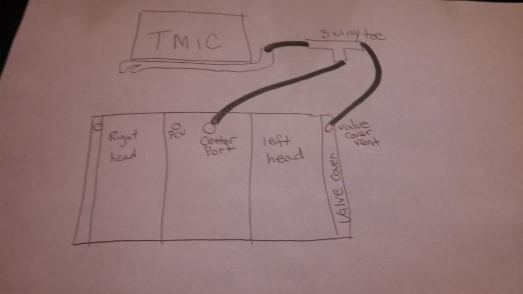
So I shouldn't do as the picture I posted before.
I found a big thread on nasoic and found this:
It should be blocked. That port has no oil separator like ALL THE REST OF THE PCV PORTS because it isn't a pcv port. In fact that port is directly above the crankshaft and massive quantities of oil gets slung up into that port. Which is the exact opposite of what you want.
I don't understand why it's so hard for everyone to understand.I have gone into great depth explaining the function of those ports and it is very simple.
If you have usdm s20 heads, you don't have avcs, you don't have the extra balance port on your valve cover and don't shouldn't try to use the balance port on the ej257 block. If you do what the guy two posts up drew on paper, you'll consume more oil than normal. If you add ports to your valve covers, you can use the balance port.
So I shouldn't do as the picture I posted before.
Last edited by goffemannen; Jun 6, 2014 at 05:27 PM.
Yeah I just did some research for you.
On the classic you have the breather system as follows:
There is a pipe which is connected to the intake hose near the power steering pump. The pipe splits into two and goes to each head.
You then have the crank breather. This is divided into two. There is a small opening which leads back to the intake hose just before the turbo. There is a bigger opening which is connected to the throttle body via a one way valve (PCV Valve).
On boost and full throttle the PCV is closed. The pressure in the crank case exits the engine via the hose into the intake hose pre-turbo. It may also vent a bit through the heads but not much.
When you are off boost and there is vacuum in the intake manifold the PCV opens and the vacuum pulls dirty air from the crank case vent into the intake manifold to burn it off in combustion. This causes a vacuum in the crank case and clean air is sucked into it via the two head vents. As the head vent pipes and the two ways the crank vent can vent are all connected to system post MAF is is all read equally (no air escapes after the MAF has accounted for it).
If you VTA then you lose the metered air.
If you VTA and don't seal the PCV you will suck unmetered air in.
If you VTA you lose the vacum of the PCV which means new clean air is not introduced into the engine and the old acidic air will increase wear.
Now the AVCs heads:
The system works the same BUT you have an extra vent hole on each head and one on the crank. These three extra vents link into one pipe. This equals or balances the pressure across all three spaces.
So..... you can block it on your engine as you don't have the extra head vents.
Thread Starter
Scooby Regular
Joined: Feb 2010
Posts: 376
Likes: 0
From: Sweden
Sounds correct and is what i have read. But some guys on in the nasoic thread have made 1 extra port on each valve cover to be able to use the extra port on the block to balance the pressure. And they also say that that is the way to do it and not block the port on the block.
Link to the thread. http://forums.nasioc.com/forums/show...1977948&page=7
Link to the thread. http://forums.nasioc.com/forums/show...1977948&page=7
Trending Topics
Sounds correct and is what i have read. But some guys on in the nasoic thread have made 1 extra port on each valve cover to be able to use the extra port on the block to balance the pressure. And they also say that that is the way to do it and not block the port on the block.
Link to the thread. http://forums.nasioc.com/forums/show...1977948&page=7
Link to the thread. http://forums.nasioc.com/forums/show...1977948&page=7
Obviously you would need to remove the covers to do this and clean the covers out properly to prevent any debris getting in the heads.
To be honest the three chambers (heads and crank case) are all linked via oil return ways anyway... but I guess there is an advantage to balancing them over the top otherwise subaru wouldnt have done it. However it may just be something thats needed due to the AVCs system? The classics seem to work fine without the balancing?.

Thread
Thread Starter
Forum
Replies
Last Post