Boost Selenoid - Boost loss and poor tickover
#1
After some advice on a boost/tickover - running a Simtek ECU on a stage rally car which has 34mm restrictor in the VF34 turbo. S20C engine with FMIC aside from that standard internals.
Engine has been suffering from a very low tick over recently (stalls if your not careful to give it a few revs before it stabilises) and also from very low boost. around 0.5 bar instead of it's previous 1.25+ bar
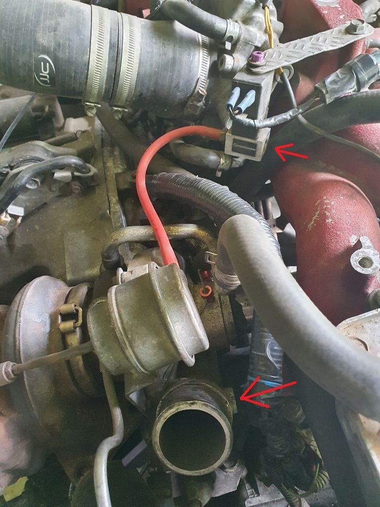
Doing all the usual checks and I noticed that the pipe from the 2 port boost selenoid (Norgren) coming from the turbo was not connected. I think it must have fallen out as I was (awkwardly) re-fitting the turbo recently.
First question - could this be the cause for the lack of boost ? the arrows on the first pic show where the pipe should have been. I understand that it opens the dump valve to release pressure but could it be that without the boost feed it would be stuck open perhaps ?
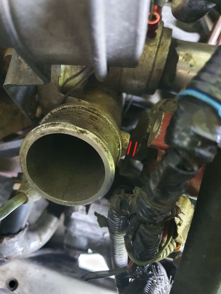
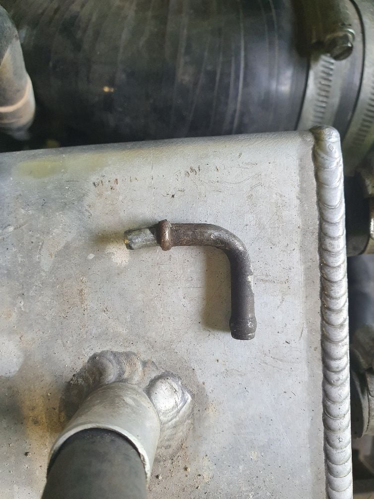
The third pic shows the pretty dodgy looking nub that fits into the turbo. it's not screw fit so not surprised it dropped out and to make matters worse it really doesn't fit in between the turbo and the manifold from the condition of the pipe it's been rubbing really badly on the elbow against the manifold.
Second question - i'm wondering whether i should cap off the current location and fit a proper threaded connection does this need to be as close to the turbo outlet ? could this be fitted slightly further out towards the intercooler or does it need to be very close to the turbo ?
Last edited by astrarally; 19 May 2022 at 02:38 PM.
#2
Looking at various pics of other VF34 turbos it looks like the elbow is a standard part. i'm wondering why there's such a lack of space on my setup as i've got a standard intake manifold
#4
Scooby Regular
VF34 is a factory turbo so no reason to be an issue against the manifold unless you have an odd exhaust manifold / up-pipe pushing it closer for some reason??
all VF turbo's have that 90deg outlet sweated in so has had some mishandling at a guess for it to be loose??
all VF turbo's have that 90deg outlet sweated in so has had some mishandling at a guess for it to be loose??
#5
It's an odd one - the up-pipe is RCM and it's in standard position as the usual bracket in place to secure to the block. comparing with my old car it certainly looks like the flange and studs are in exactly the same place
that suggests inlet manifold is different then - i'll get some more pics to see if anyone can give me a clue.
I've "re-shaped" the 90deg outlet for now - bit of heating and careful bending turned it into an L shape which gives it enough room to sit in, and with the turbo fitted seats rights up against the manifold
#7
VF 34 came as std with the RA model 2003 car but only in jdm.
I still have my VF 34.
It does not rub on the newage manifold. Either with a grimmspeed up pipe or stock up pipe
VF 35 came std on sti bugeye
I still have my VF 34.
It does not rub on the newage manifold. Either with a grimmspeed up pipe or stock up pipe
VF 35 came std on sti bugeye
Last edited by silver6933; 30 May 2022 at 01:03 PM.
Trending Topics
#8
Scooby Regular
not strictly correct..........
VF35 was used on all new-age 2.0STi for the UK / EU market so both Blob & Bug
VF34 was used on the last of the Bug JDM RA's (can't recall off hand what std Spec-C got)
JDM wise by MY03 they were ALL twin scroll so VF36 or VF37 for the more regular STi's
VF35 was used on all new-age 2.0STi for the UK / EU market so both Blob & Bug
VF34 was used on the last of the Bug JDM RA's (can't recall off hand what std Spec-C got)
JDM wise by MY03 they were ALL twin scroll so VF36 or VF37 for the more regular STi's
#9
Scooby Regular
#10
Scooby Regular
#11
I wonder if i've somehow got an inlet manifold which isn't quite compatible with the VF34's clearance. as mentioned the up pipe flange is definitely in the OE position (with the bracket). car is away at the tuners now but will get some more pics up asap. it's an s20c block - i'm assuming there were quite a few inlet manifold options on top of the different turbo options ?
Re the first pic i took the turbo was not mounted in place. the second pic showing the 2 red lines is where it's in place - definitely not enough room for the 90 degree elbow without the "re-shaping"
Re the first pic i took the turbo was not mounted in place. the second pic showing the 2 red lines is where it's in place - definitely not enough room for the 90 degree elbow without the "re-shaping"
Last edited by astrarally; 01 June 2022 at 01:52 PM.
Thread
Thread Starter
Forum
Replies
Last Post
chrisdicko
General Technical
5
09 October 2012 08:35 PM


