When you click on links to various merchants on this site and make a purchase, this can result in this site earning a commission. Affiliate programs and affiliations include, but are not limited to, the eBay Partner Network.
Hi, I'm trying to fix my oil temp and oil pressure gauges on my pod as when the ignition turns on they both just go straight to max, I'm presuming it's the wiring so I'm trying to get the gauges out to have a look. Iv looked at the sensors in the engine bay and apart from a bit of leaking on the oil pressure sensor (which I'm gonna fix) the engine side seems ok. My prob is I'm not quite sure how these dials come out and it feels like I'm gonna snap something everytime I try to get them out, does anyone know what the average way of fitting these is. It looks like some sort of glue down the pod side. I managed to pul the left hand side of one of the gauges but it doesn't feel like that should be done so I don't want to break it. Before I started I figured they would just be pushed in with some sort of clip but it's possible some cowboy has done the installation. Any one know the wiring for the pods?
Id try to gently prise it apart as it does look like glue. It could be silicone sealer which is easier to deal with. As for fixing in place, i used strips of stick on Velcro on each side .Worked well and allows eary removal of the pod(till it was nicked anyway)
Ye it feels like a glue cause when you put a flat screw driver down the side and twist gently you can feel it cracking the seal. I will just have to see if I can prise it off. Nice idea with the velcro if it sits flush.
Wiring will prob depend on the make. If they are a version other than Defi or similar, theres prob only 3 wires. One for lighting , an earth and a signal one to go to the sender.
Thing is ,wiring wise, keep it simple. From each light terminal,fit a shrt piece of wire and join these up, preferably soldering and shrink tubing. Join these 3 wires to a single wire long enough to reach a wire for the sidelights. Do the same with the earth , there should be a suitable earthing point under the place where the cubby hole was. The last wires are your sensor signal wires, which obviously run from each sensor needing one. If you have problems with oil temp or pressure with no reading, you may have to run individual earths t get any signal. One addition i made, small one, but i fitted a dimmer as i found the gauge lights too bright and distracting. . hope this helps
Well it was defo super glue, I think the fella who fitted it must of been wearing a cowboy hat as he did it . Least it's off now so I can start fixing it properly.
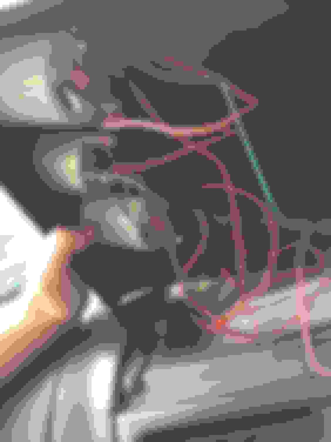
Here is the wiring to my gauges, does any one know what the wiring diagram should be?? I think the wires are black, red, orange and green or yellow. The dials are motor meter racing.
And i dont want to be the bringer of bad news but, it looks like the flange around the edge of the pod , has been hacked off. So, my suggestion of using velcro or magnetic tape prob wont work as theres sod all to fix too. In my opinion, if you dont want to glue it back on, which you dont want to do, youll need a new pod, I would, as all that will happen is that the pod will just keep falling off and ,in your frustr, youll reach for super glue , which is prob whats happened before .
Also the oil temp sensor has 2 wires coming from it, I would presume there both the same sensor so that you can have 2 if you want and it would earth through the car like the other sensors but on mine the fella has one going to the temp sensor and the other is earthed to the body?
Red should be 12+ , Black- ve, Orange prob goes to the lighting , greencould be triggers from the sensor as the boost gauge hasnt got one
Could the orange go to ignition? It's only because there is a wire going from under the steering wheel to the dials so I'm presuming that has been wired to ignition rather than lights
And i dont want to be the bringer of bad news but, it looks like the flange around the edge of the pod , has been hacked off. So, my suggestion of using velcro or magnetic tape prob wont work as theres sod all to fix too. In my opinion, if you dont want to glue it back on, which you dont want to do, youll need a new pod, I would, as all that will happen is that the pod will just keep falling off and ,in your frustr, youll reach for super glue , which is prob whats happened before .
I recon if I use a little silicon it should bed into it ok and easy enough to get of if I ever need too.
Id doubt if there would be 2 ignition feeds though.From what i can make out from the photo, one wire has more of a red trace on it , the other is more red. Try to match the end coming from the ign to the ones on the gauges. I f you have a tester or a lamp , see what happens with the tester when you turn the lights on. One will go to the lights and it would be unusual to have the gauge lightsgoing to the ign switch when its so much more convenient to take the feed from behind the area youre working in. The silicone may work , but you may have to wait a few hours for it to cure properly so your handiwork doesnt finish up on your lap
Ye I think iv got my head around it a bit more now, I think its 1 wire from the ignition which will go to the reds then the blacks to earth and the greens to sensors and the orange to lights. I think where its going wrong is that the fella has 2 feeds from the sensor and has earthed one. I will try later if I get a chance disconnecting that and see how I get on, Think I will also clean up the wiring with some shrink tube. I am right in thinking if there is 2 feeds from the oil heat sensor on the engine that they will both be giving the same readout which is just a sensor wire and that neither should be going to an earth? Also where do people normally tap into for the lights? Thanks for all your help btw its much appreciated, hopefully this link might help others if they get stuck too.
Oil temp sensor should just have 1wire from the little tag on top or a short threaded piece with a nut. Sometimes, if a sealing tape has been put on the threads (PTFE)the sensor, it will prevent the sensor from earthing , which prevents proper operation. Good idea on the wiring as it loks very poorly done. The pickup for the lighting is taken fromanywhere theres a feed for the sidelights. Just underneath the cubby hole place thereswiring there that can be used.
Iv cut the black wire from the oil heat sensor too the earth cables and that has stopped the needles bouncing once the ignition is on and iv tested the red cable from under the dash and it is a 12v ignition cable so were going in the right direction haha. When I turn the ignition on and just have the earth and ignition wire connected to the oil pressure gauge it lights up and also the dial stays at max. The other thing I noticed is that the orange cable is slightly thicker than the green and red so I'm wondering if the orange is what should attach to the 12v ignition wire? Also if I try connecting a 12v wire to the sensor wire accidentally will it blow the **** out of the dials?

 15 July 2015, 09:50 PM


 . Least it's off now so I can start fixing it properly.