Routing cables to engine bay for PSI3 sensors
 07 July 2008, 06:44 AM
#1

Hi,
What is the best way to route the cables for the oil temp and pressure sensors to the engine bay?
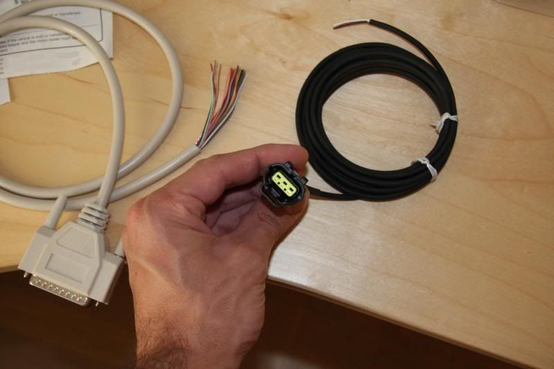
How big are the holes in the bulkhead? The reason I am asking is because I need to solder the cables in the attached pic. Is the hole big enough for the connector to go through once I have soldered them or should I pass the cable through first (and where from) and then do the soldering in the car? (more of a pain)
Cheers
What is the best way to route the cables for the oil temp and pressure sensors to the engine bay?
How big are the holes in the bulkhead? The reason I am asking is because I need to solder the cables in the attached pic. Is the hole big enough for the connector to go through once I have soldered them or should I pass the cable through first (and where from) and then do the soldering in the car? (more of a pain)
Cheers
Last edited by fpan; 07 July 2008 at 07:26 AM.
 07 July 2008, 08:17 AM
#2

The largest & most convenient one is down by the pedals - about 1" in size. It comes out by the downpipe , so needs sleeving with some heat protection.
Tis easy enough to knock the insulation and bung out the way and push that connector (presumably not the parallel one) through to see if it works.
Nick
Tis easy enough to knock the insulation and bung out the way and push that connector (presumably not the parallel one) through to see if it works.
Nick
 07 July 2008, 02:16 PM
#5
Scooby Regular
iTrader: (1)
Join Date: Oct 2004
Location: Half way up
Posts: 4,791
Likes: 0
Received 0 Likes
on
0 Posts
I did mine as Nick says through grommet up behind pedals through bulkhead. If you look from engine bay you'll see it. It may already have some cable going through it.
I then routed the boost gauge wiring along bulk head (following loom) to n/s to come around IC to sender location.
The oil temp and pressure routed inside of o/s suspension turret (again following existing loom) to sender locations above cyl 3 and under alternator (going under coolant expansion tank). I spiral wrapped them together and using cable ties where necessary.
Looks very oem, even if I do say so myself..
08 July 2008, 08:46 AM
#6
I just had a chat to Powerstation and they prefer the method of the oil filter sandwich plate (instead of above cyl#3). It is easier to fit the sensors and you can keep the OE oil pressure sensor.
Also both sensors are located at the same place.
Has anyone had any problem with this setup? I would be interested to know.
Thanks
Also both sensors are located at the same place.
Has anyone had any problem with this setup? I would be interested to know.
Thanks
08 July 2008, 09:31 PM
#7
Scooby Regular
iTrader: (1)
Join Date: Oct 2004
Location: Half way up
Posts: 4,791
Likes: 0
Received 0 Likes
on
0 Posts
Not wanting to disagree with PS, but you can fit an aftermarket sensor (ie Defi/PSi) along with the OEM using an adaptor from LMA.
Neither oil temp (cyl 3 main gallery) or pressure are difficult to fit if you have half a clue.
Fitting using a sandwich plate, IMHO, adds the risk of damaging the senders during filter/oil change..
Neither oil temp (cyl 3 main gallery) or pressure are difficult to fit if you have half a clue.
Fitting using a sandwich plate, IMHO, adds the risk of damaging the senders during filter/oil change..

Thread
Thread Starter
Forum
Replies
Last Post
shorty87
Full Cars Breaking For Spares
19
22 December 2015 11:59 AM
MightyArsenal
Wheels, Tyres & Brakes
6
25 September 2015 08:31 PM