Notices

Vacuum hose layout

Thread Tools
 
Search this Thread
 
Old 25 May 2021, 05:05 PM
  #1  
ByPrOdUcT
Scooby Newbie
Thread Starter
 
ByPrOdUcT's Avatar
 
Join Date: May 2021
Location: Wellingborough
Posts: 2
Likes: 0
Received 0 Likes on 0 Posts
Default Vacuum hose layout

Hello

I have a 99 turbo 2000 WRX that I have been trying to put back together now for an entire year and I am stuck on what I am hoping is the last few steps. I am trying to connect up the vacuum hose/ intake setup back together, some of which was already in place and some that wasn't
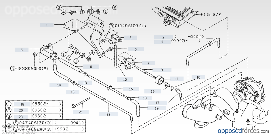
I have made a little diagram of how it is currently connected and I have an idea of what I need to change but an really not sure and don't wanna damage her after all the work so far.


I think that I need to
connect 5 to 7
3 should go to the return on the "BOV"
1 should go to the vacuum for the "BOV"
I have search the pages and put this together so far with what i have found from diagrams of not quite the same car, any help would be very much appreciated.
thank you
Old 25 May 2021, 06:07 PM
  #2  
1509joe
Scooby Regular
iTrader: (2)
 
1509joe's Avatar
 
Join Date: Jan 2009
Location: Not sure
Posts: 3,296
Received 278 Likes on 248 Posts
Default

This is all the same apart from this being a three port boost solenoid. You will need a T piece and a pill from the turbo to the actuator.

Last edited by 1509joe; 25 May 2021 at 06:10 PM.
Old 25 May 2021, 06:46 PM
  #3  
Don Clark
Scooby Regular
 
Don Clark's Avatar
 
Join Date: Feb 2003
Location: Harpenden
Posts: 7,559
Received 747 Likes on 620 Posts
Default


Above
Pipes 5, 10 and 2 go to turbo inlet pipe.
Pipes 9 &11 connect to the heads

Old 25 May 2021, 06:52 PM
  #4  
Don Clark
Scooby Regular
 
Don Clark's Avatar
 
Join Date: Feb 2003
Location: Harpenden
Posts: 7,559
Received 747 Likes on 620 Posts
Default


Old 25 May 2021, 06:58 PM
  #5  
1509joe
Scooby Regular
iTrader: (2)
 
1509joe's Avatar
 
Join Date: Jan 2009
Location: Not sure
Posts: 3,296
Received 278 Likes on 248 Posts
Default


Another one. Should be the same as yours.
Now Don your at it

Last edited by 1509joe; 25 May 2021 at 06:59 PM. Reason: Don Clark
Old 25 May 2021, 08:37 PM
  #6  
Don Clark
Scooby Regular
 
Don Clark's Avatar
 
Join Date: Feb 2003
Location: Harpenden
Posts: 7,559
Received 747 Likes on 620 Posts
Default

Originally Posted by 1509joe
Another one. Should be the same as yours.
Now Don your at it
Depends if OP's is a MY99 or MY00 Turbo 2000
Old 30 May 2021, 01:05 PM
  #7  
ByPrOdUcT
Scooby Newbie
Thread Starter
 
ByPrOdUcT's Avatar
 
Join Date: May 2021
Location: Wellingborough
Posts: 2
Likes: 0
Received 0 Likes on 0 Posts
Default

Thanks for all the help and diagrams, I think I understand where everything is meant to go now.

I have connected it all up as shown last night with the pipes and clamps I already had and I can now start the car but it won't idle, it starts first time then as it drops to 1k RPM is starts to stutter and die, if I rev it or try to raise the RPM it back fires a few times and then dies anyway.

I have ordered a bunch of new clips and hoses as well as a MAF (just in case). Once they arrive and I put it all on hopefully it will be okay.

one thing I did notice last night that I didn't put in my diagram was the vacuum off the throttle body that seems to have a vacuum hose attached to nowhere sitting on it. 🤨

Thank you all again. 🙂

Last edited by ByPrOdUcT; 30 May 2021 at 01:07 PM.
Old 01 June 2021, 11:20 AM
  #8  
Don Clark
Scooby Regular
 
Don Clark's Avatar
 
Join Date: Feb 2003
Location: Harpenden
Posts: 7,559
Received 747 Likes on 620 Posts
Default

The only pipes attached to the throttle body, AFAIK, apart from the obvious inlet air pipe are the two cooling water connections.


Last edited by Don Clark; 01 June 2021 at 11:22 AM.
Old 01 June 2021, 11:32 AM
  #9  
1509joe
Scooby Regular
iTrader: (2)
 
1509joe's Avatar
 
Join Date: Jan 2009
Location: Not sure
Posts: 3,296
Received 278 Likes on 248 Posts
Default

On the earlier cars there was a small brass 4mm ish pipe for the purge system. Maybe someone has fitted an earlier throttle body. I forget when it changed but the throttle cable is on the opposite side on the earlier cars which may help. Pipe I on above diagram.

Last edited by 1509joe; 01 June 2021 at 11:52 AM.
Old 01 June 2021, 01:45 PM
  #10  
Don Clark
Scooby Regular
 
Don Clark's Avatar
 
Join Date: Feb 2003
Location: Harpenden
Posts: 7,559
Received 747 Likes on 620 Posts
Default

Originally Posted by 1509joe
On the earlier cars there was a small brass 4mm ish pipe for the purge system. Maybe someone has fitted an earlier throttle body. I forget when it changed but the throttle cable is on the opposite side on the earlier cars which may help. Pipe I on above diagram.

Old 01 June 2021, 02:00 PM
  #11  
Don Clark
Scooby Regular
 
Don Clark's Avatar
 
Join Date: Feb 2003
Location: Harpenden
Posts: 7,559
Received 747 Likes on 620 Posts
Default


Old 01 June 2021, 02:16 PM
  #12  
1509joe
Scooby Regular
iTrader: (2)
 
1509joe's Avatar
 
Join Date: Jan 2009
Location: Not sure
Posts: 3,296
Received 278 Likes on 248 Posts
Default

Thats the wee pipe sitting right on top in the centre ot the throttle body. With a right angle bend on it.
Old 01 June 2021, 05:10 PM
  #13  
Don Clark
Scooby Regular
 
Don Clark's Avatar
 
Join Date: Feb 2003
Location: Harpenden
Posts: 7,559
Received 747 Likes on 620 Posts
Default

Originally Posted by 1509joe
Thats the wee pipe sitting right on top in the centre ot the throttle body. With a right angle bend on it.
MY97/98


Related Topics
Thread
Thread Starter
Forum
Replies
Last Post
jjayokocha
General Technical
1
18 June 2015 02:01 PM
Robbie 'Kirky' McClure
General Technical
5
03 September 2013 12:33 PM
MattyB1983
ScoobyNet General
10
04 March 2012 03:03 PM
14N-FR
ScoobyNet General
2
30 March 2011 04:05 PM


Quick Reply: Vacuum hose layout


All times are GMT +1. The time now is 11:37 PM.