

Boost Gauge Install help please!


Thread Starter
Scooby Regular
Joined: Dec 2014
Posts: 91
Likes: 0
From: Winchester
Hi Guys, I am looking to install a boost gauge on the pillar of my 2003 sti but I'm not sure where to wire it up.
Are there any diagrams or anyone that can explain in a bit of detail (I'm a bit of an electrical dumbass) on how to do it?
Thanks, Dave.
Are there any diagrams or anyone that can explain in a bit of detail (I'm a bit of an electrical dumbass) on how to do it?
Thanks, Dave.

Scooby Newbie
Joined: Jun 2005
Posts: 14
Likes: 0
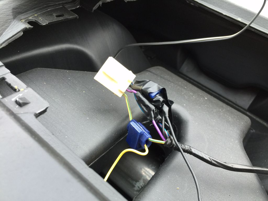
I can't really advise beyond this, but I removed a boost gague that was in one of the centre vents from my 2003 wagon and the lighting for the gauge was tapped from the clock:
Can't say if this the best way to run it, but it appeared to work ok for as long as it took me to drive back from collecting the car
Can't say if this the best way to run it, but it appeared to work ok for as long as it took me to drive back from collecting the car


Do it right though...the above is a right pig's ear.
The wiring on Scoobs uses the modern thinwall stuff, so the tap-in connectors need to be red, not blue.
Or better still, remove insulation, wrap wire round, solder and heatshrink.
The wiring on Scoobs uses the modern thinwall stuff, so the tap-in connectors need to be red, not blue.
Or better still, remove insulation, wrap wire round, solder and heatshrink.
Solder is the way forward. Those scotchlock things should be banned.
Trending Topics

Scooby Regular
Joined: Jul 2011
Posts: 2,514
Likes: 1
From: harlow
Likely have daylight running and nighttime dimming, not needing to wire it up like that, just have it in nighttime dimming all the time.
Thread Starter
Scooby Regular
Joined: Dec 2014
Posts: 91
Likes: 0
From: Winchester
There is a diagram of sorts but not all that clear to a noob like me, hence why I'm a little concerned about hashing it up!
So Boosted, would you recommend running wires to the clock or is there somewhere closer to the drivers pillar that would be better?
So Boosted, would you recommend running wires to the clock or is there somewhere closer to the drivers pillar that would be better?
I picked up connections for my boost gauge at the instrument cluster. But, I have a lot of electronic test equipment to identify stuff, appropriate tools and also experience with soldering. Have you got anything like a simple multimeter and a soldering iron?

Scooby Regular
Joined: Jun 2014
Posts: 566
Likes: 0
From: england
Wire it to the clock. Drop a peice of string down aswell as the boost gause wires. Then tie them togethher and pull the boost gause wires up. Then tap the live wire into the ignition wire for the clock (not constant live) the earth to the earth and the third one i wouldnt worry about.
Scooby Regular
Joined: Jun 2014
Posts: 566
Likes: 0
From: england
The ignition you need to attach your live from the boost gauge is the yellow wire at the bottom of the clock harness.
The earth is the black wire two above it (seccond from top)
If you want to wire in the third dimmer wire its the pink wire above the ignition hope that helps
The earth is the black wire two above it (seccond from top)
If you want to wire in the third dimmer wire its the pink wire above the ignition hope that helps

On the back of the clock on new ages right beside the clip it will tell you what wire is what
If your going to install a single gauge are you fitting it onto the a pillar or steering cowl?
Steve
If your going to install a single gauge are you fitting it onto the a pillar or steering cowl?
Steve
Scooby Newbie
Joined: Jun 2005
Posts: 14
Likes: 0
Wire it to the clock. Drop a peice of string down aswell as the boost gause wires. Then tie them togethher and pull the boost gause wires up. Then tap the live wire into the ignition wire for the clock (not constant live) the earth to the earth and the third one i wouldnt worry about.


Scooby Regular
Joined: Nov 2012
Posts: 1,262
Likes: 0
From: leeds
Scooby Regular
Joined: Dec 2014
Posts: 124
Likes: 0
From: Co Durham
One of these is useful if you don't have a meter: http://www.ebay.co.uk/itm/CAR-LIGHT-...item418dafabb7
It can be used to find a live, both permanent and switched.
As for soldering, so long as the wires to be joined are clean, it's simple.
here's a foolproof method:
Strip back an area of the wire to be joined to, about 10mm is fine. I do it using a Stanley type knife, shave along gently.
Now strip back about 15mm of the wire you want to join to it.
Twist the new wire round the one to be tapped into, making a neat join.
Now cut off about 10mm of solder wire and wrap that round the join.
Place soldering iron under the join in contact with solder. You will see it melt, wait until it flows., remove soldering iron and keep joint still until solder goes hard, (moving it too early is the main cause of "dry-soldered" joints which give poor results).
You can't really heatshrink it, unless your wire to be joined into has a free end. Best stuff to use is self-sealing tape, otherwise some electrician's tape is fine.
Scooby Regular
Joined: Jun 2014
Posts: 566
Likes: 0
From: england
Or you can poke a hole threw the wire your tapping into.
Twist the wire from the boost gauge into a thin line then poke it therew the hole.
Then close the loop you made then twist the wire around.
Tape over it and imo is as strong as soldering this age old method
Twist the wire from the boost gauge into a thin line then poke it therew the hole.
Then close the loop you made then twist the wire around.
Tape over it and imo is as strong as soldering this age old method
Thread Starter
Scooby Regular
Joined: Dec 2014
Posts: 91
Likes: 0
From: Winchester
Wow, thanks guys, you have been a massive help. I think i'm gonna do it this weekend weather permitting. Would you say that the pipe by the dump valve or the inlet manifold would be the best place to attach the pipe to the gauge?
Always bear in mind that a poor connection results in high resistance, and that high resistance results in heat, and that heat can result in destroyed electrics or fire

Scooby Regular
Joined: Jun 2014
Posts: 566
Likes: 0
From: england
Then the long peice of vacume hose goes from the bottom of your t.peice threw the fire wall and up the pillar!
No problem. There realy aint a good soild guide anyware online. Why you would cut into the vacume for the dumpvalve on the wrong side of the engine bay i dont know