
Engine Stage 1


Thread Starter
Orange Club
Joined: Oct 1998
Posts: 13,763
Likes: 1
Note: If you have problems changing pages on this article, please ensure you have the following option set in your USERCP -> "Number of Posts to Show Per Page" set to "Use Forum Default"
Well, we have to begin somewhere and what better stage to start then modifications to the Engine! Looking at basic, well chosen modifications lets see what is possible...... I think you may be surprised!
SUPPORT AND SUPPLY OF PRODUCTS AND SERVICES FOR ENGINE - STAGE 1

Powerstation - Rolling Road Facility, Mapping, Technical Help/Guidance, Product Supplier, Workshop Facilities (fitment/testing of products)

ScoobySport - Product Supplier, Technical Help

Litchfield Imports - Product Supplier, Technical Help
METHOD OF MEASUREMENT FOR ENGINE MODIFICATIONS
Perhaps the single biggest bone of contention is how we would decide to measure/test for any increases (and of course decreases) in power , when looking at Engine Modifications. Several ways exist, namely use of a Rolling Road, Engine Dyno, Performance Meters and the regularly used �**** dyno� (for those that are not familiar with this, it is the term given to the �just driven my car and it feels so much quicker now�. It must be 400bhp�). While this list is not the entire range of methods available, it gives you an idea in the numbers of ways that are available. For the purpose of these comparisons on Engine Modifications figures, these will be attained by use of a Rolling Road, coupled with real driving feedback on the road.
 Even though we may all agree that various rolling roads will give different readings and the arguments that RR figures at X are incorrect and Y are correct is meaningless to a degree. Although many conditions even on the same rolling road can cause changes in figures, we need
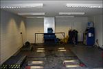
 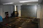 something we can use to compare. Obviously the more conditions you can stabilise, the better your figures will be representative. Bearing this in mind, it was decided to approach the new facility at Powerstation. Powerstation now provide a dyno cell, which with the installed
 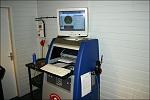 ventilation system strives to provide a more stable running environment that can be repeated time and time again..... perfect for the tests being made within this article. The ventilation system comprises of a huge extraction fan, large and powerful induction fan and to finish it off a specific unit especially for us top mounted intercooler boys.
Well, we have to begin somewhere and what better stage to start then modifications to the Engine! Looking at basic, well chosen modifications lets see what is possible...... I think you may be surprised!
SUPPORT AND SUPPLY OF PRODUCTS AND SERVICES FOR ENGINE - STAGE 1
Powerstation - Rolling Road Facility, Mapping, Technical Help/Guidance, Product Supplier, Workshop Facilities (fitment/testing of products)
ScoobySport - Product Supplier, Technical Help
Litchfield Imports - Product Supplier, Technical Help
METHOD OF MEASUREMENT FOR ENGINE MODIFICATIONS
Perhaps the single biggest bone of contention is how we would decide to measure/test for any increases (and of course decreases) in power , when looking at Engine Modifications. Several ways exist, namely use of a Rolling Road, Engine Dyno, Performance Meters and the regularly used �**** dyno� (for those that are not familiar with this, it is the term given to the �just driven my car and it feels so much quicker now�. It must be 400bhp�). While this list is not the entire range of methods available, it gives you an idea in the numbers of ways that are available. For the purpose of these comparisons on Engine Modifications figures, these will be attained by use of a Rolling Road, coupled with real driving feedback on the road.
Last edited by ex-webby; Feb 19, 2008 at 05:16 PM.
Thread Starter
Orange Club
Joined: Oct 1998
Posts: 13,763
Likes: 1
If you are not already aware, power figures on Rolling Roads are part measured and part calculated. For the purpose of this article we will be showing Flywheel and Torque figures. One last point worth mentioning is that both peak figures (regardless of measurement) and to a degree even full graphs of delivery do not tell the whole picture. How the car responds and drives on the road in real life driving scenarios, is equally as important. As and when (when applicable) we will also be driving the car and testing on the road during major steps in the Engine Modifying process, to get more feedback and information.
STAGE 1 – ENGINE MODIFICATIONS
Re-mapping
For this stage of testing and comparison we will be looking primarily at bolt on modifications, with the exception of ECU remapping. Any ECU mapping will be completed using the standard OEM ECU in conjunction with the ECUTEK software, this allows access and change of the ECU parameters as desired. For obvious reasons this needs to be done professionally by people that know exactly what these changes mean and what they will affect. With this in mind, ECU re-mapping will be undertaken by Powerstation.
The standard ECU on newage Impreza’s is incredibly flexible and comprehensive. It was not that long ago that the only way to achieve full control over various parameters, was to purchase an aftermarket ECU, primarily one aimed at the motorsport market. Luckily for us and with the development of ECUTEK this is no longer an issue for our level of modifications. This is all good news for us guys, as it means we can then spend our money on other things!!
For the majority of us we don’t really care what this side entails. As long as we get the expected results who cares what parameters have to be changed and for what reason……but equally there are a number of us who are interested.
The black art of engine management has moved from the old days of physically changing ignition and fueling, by means of spanners.... now a new tool is being used.... the all powerful Laptop!
Last edited by ex-webby; Jan 28, 2007 at 04:41 PM.
Thread Starter
Orange Club
Joined: Oct 1998
Posts: 13,763
Likes: 1
Of course while the tools may of changed the logic and physics have not. The changing of x,y,z parameter, whether by spanner or keyboard will have the same postive or negative result. Sure, a lot of people take computers as a way of life (the tool to reprogram the ECU), but this does not take away the fact that adjusting/mapping is not a task to be undertaken by a person with no knowledge of this subject.
On a turbo charged engine, the basic's were that of altering Ignition, Fuel and Boost achieved more power. While the basic's are still the same, so many other features are now available via various ECU's. Via the use of the ECUTEK software, these very useful features can now be unlocked and put to good use (dependant on model year).
An example of what is now on offer with this type of mapping solution is that of in-gear compensation......
Many people may have realised with a Turbo car, is that different gears produce different boost levels and different boost climb rates. This is one area that ECUTEK can help with. Boost levels and climb rates are not static, as it depends on engine load. The greater the load the quicker the boost will climb and the more effeciently a boost target will be met. This can be seen on cars without this facility, as boost achieved (and the way it climbs) will be less (and slower) in say gears 1st, 2nd & 3rd as it is to 4th, 5th (and of course 6th). By adjusting facilities in ECUTEK (which allows certain trim levels of boost control whilst in specific gears) it is now possible to achieve close on exactly the same boost levels and climb in 2nd, 3rd (for example) as in 4th, 5th and 6th. Sound's rather simple doesnt it.... but the difference this makes to driveability is amazing.
Whilst this is one of the more simplistic advantages (to explain) it highlights what extra facilities the mappers now have at their fingertips.
Last edited by ex-webby; Jan 27, 2007 at 01:58 PM.
Thread Starter
Orange Club
Joined: Oct 1998
Posts: 13,763
Likes: 1
TEST 1 - Base Figure
To enable use to gauge what engine modifications have done what, we need a base figure to relate to. The Spec C in it’s current state of tune at this point had already been modified with a UK Fuel remap using the ECUTEK software and first generation Miltek Twin Scroll Sports Cat 2 1/2 “ exhaust system. With this in mind it was decided to keep the map as it was (until of course we needed/had to remap) but to change the exhaust system to a standard version. The ECU map was not representative as standard, but since this map would be used for all comparisons until such time a re-map had to be made, it was not seen as a major problem. Any comparisons would be deemed comparative, regardless of the base map and as long as each test was completed (where possible) with the same map (PowerStation would normally specify a remap when adding modifications, to get the best out of such modifications).
Unless otherwise specified, all comparisons will be completed using Optimax as the fuel.
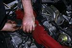
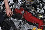
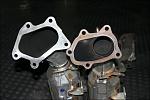 The original MY03 exhaust is now somewhat different to that of a later model, with some major changes regarding the downpipe. As you can see from the pictures to the side the MY03 neck design (on the right) is totally different to the MY05 (on the left) neck design. The MY05 neck is open neck, while the MY03 neck has a flat face
 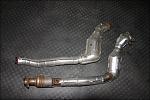 which would sit against the wastgate exit. Admittedly the MY03 downpipe is from a non twin scroll engine (top) and the MY05 downpipe (bottom) is from a twin scroll engine shown below, but the design concept was the same for the twin scroll variety for that year.
 Strangely enough the MY05 standard system now has an open neck design, which is something that has been used by many after market exhaust manufacturers for a while now.
Since the latest MY05 standard system was deemed as being the most efficient, this was the one that was put on the Spec C for base lining.
To enable use to gauge what engine modifications have done what, we need a base figure to relate to. The Spec C in it’s current state of tune at this point had already been modified with a UK Fuel remap using the ECUTEK software and first generation Miltek Twin Scroll Sports Cat 2 1/2 “ exhaust system. With this in mind it was decided to keep the map as it was (until of course we needed/had to remap) but to change the exhaust system to a standard version. The ECU map was not representative as standard, but since this map would be used for all comparisons until such time a re-map had to be made, it was not seen as a major problem. Any comparisons would be deemed comparative, regardless of the base map and as long as each test was completed (where possible) with the same map (PowerStation would normally specify a remap when adding modifications, to get the best out of such modifications).
Unless otherwise specified, all comparisons will be completed using Optimax as the fuel.
Since the latest MY05 standard system was deemed as being the most efficient, this was the one that was put on the Spec C for base lining.
Last edited by ex-webby; Jan 28, 2007 at 04:41 PM.
Thread Starter
Orange Club
Joined: Oct 1998
Posts: 13,763
Likes: 1
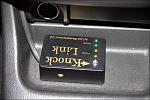
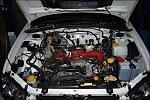
As the task of removing the Miltek exhaust system consisted of removal of the Top Mounted Intercooler (TMIC) to gain access to the turbo heatshield and surround, it was decided at this point to fit a Knock Link.
A Knock Link is a device that is used to measure or listen for detonation. Detonation is the uncontrolled ignition of fuel in the bore (above the piston). Ignition of fuel needs to be controlled and having fuel ignite outside of this controlled environment is not good. Detonation (also known as knock) can be disasterous, causing pitting of the piston crown at best to total melt down and failure of the piston at worst. It is of course arguable that on a car that is mapped and setup correctly, why would you need a device such as this….. it’s always a comment that has both sides of the fence debating, but since I think you can never have enough warning devices and the unit works so well, coupled with the fact of test work that is being completed it was decided to install the device.
The Knock Link consists of a pick up sensor, Knock Link control unit and loom.
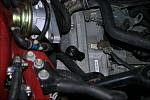 The unit is very easy to fit and really only consists of mounting the pick up and providing power to the control unit. The pick up device is basically a microphone and for this specific application is
 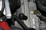 best mounted on the block underneath the TMIC (as seen in the adjacent picture).
Once the unit is wired in and mounted (position obviously down to personal choice), the unit is ready to rock.
The unit consists of a 5 stage monitoring process. Each stage consists of a number of different coloured LED’s, detailed as follows:
 1st and 2nd LED’s (Green) – Engine noise (normal operation)
3rd and 4th LED’s (Amber) – Possible detonation pending (warning level)
5th LED (Bright Red - when unlit this is white) – Detonation detected
Even though the control unit has a sensitivity trim on it, if the pick up is mounted in the recommended place (as described) adjustment should not be required.
So…. with the standard MY05 exhaust in place, the car was as standard as possible to record a base power figure.
A Knock Link is a device that is used to measure or listen for detonation. Detonation is the uncontrolled ignition of fuel in the bore (above the piston). Ignition of fuel needs to be controlled and having fuel ignite outside of this controlled environment is not good. Detonation (also known as knock) can be disasterous, causing pitting of the piston crown at best to total melt down and failure of the piston at worst. It is of course arguable that on a car that is mapped and setup correctly, why would you need a device such as this….. it’s always a comment that has both sides of the fence debating, but since I think you can never have enough warning devices and the unit works so well, coupled with the fact of test work that is being completed it was decided to install the device.
The Knock Link consists of a pick up sensor, Knock Link control unit and loom.
Once the unit is wired in and mounted (position obviously down to personal choice), the unit is ready to rock.
The unit consists of a 5 stage monitoring process. Each stage consists of a number of different coloured LED’s, detailed as follows:
3rd and 4th LED’s (Amber) – Possible detonation pending (warning level)
5th LED (Bright Red - when unlit this is white) – Detonation detected
Even though the control unit has a sensitivity trim on it, if the pick up is mounted in the recommended place (as described) adjustment should not be required.
So…. with the standard MY05 exhaust in place, the car was as standard as possible to record a base power figure.
Last edited by ex-webby; Jan 27, 2007 at 02:14 PM.
Thread Starter
Orange Club
Joined: Oct 1998
Posts: 13,763
Likes: 1
Summary of Spec
 Standard JDM Spec C MY03 Engine & Turbo
Standard Panel Filter
Standard MY05 Catted Exhaust System
ECUTEK remapped ECU with basic UK Fuel map
Peak Boost - 1.50bar
Fuel - Optimax
The Base Line figure achieved was 318.2bhp @ Flywheel with 408.2Nm (301.03 lb ft) torque
TEST 2 - Exhaust Change - Overview
One of the concepts of trying to release more power effectively and efficiently is to try and improve both the induction and exhaust side of an engine. In theory, the quicker you can get more air in and the quicker you can expell the exhaust gases out, the more efficient you can make the combustion and effectively make more power.
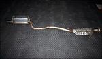
To part prove the concept (relating to exhaust gases in this case) and reality of this, we fitted the car with the straightest and most free flowing exhaust system that ScoobySport offers.
The exhaust itself is of a 3" design, from the downpipe all the way through to the backbox. The downpipe has an open neck, suited especially for the Twin Scroll turbo. To try and achieve the best flow rates, this specific system that was tested has no centre resonator and has a straighter than normal back box design. Normally the pipe work in the back box section is angled, but this design has resulted in this pipe work being as straight as possible, giving the straightest gas flow. This has a resulting finish that shows the back box exit not appearing to be "straight" as you look at the back of the car, but with the slight Jap style slash cut, this appearance is muted. This system tested also did not have any CAT's.
According to what I understood about the design process of this specific system, it's 3" design should retain low end torque, while producing higher air flow capacity. While increasing the exhaust flow, by reducing backpressure, it should minimize exhaust gases going back in to the combustion chamber resulting in better combustion (reduced backpressure increases exhaust scavenging from the combustion chamber, allowing a more efficient combustion process).
Standard Panel Filter
Standard MY05 Catted Exhaust System
ECUTEK remapped ECU with basic UK Fuel map
Peak Boost - 1.50bar
Fuel - Optimax
The Base Line figure achieved was 318.2bhp @ Flywheel with 408.2Nm (301.03 lb ft) torque
TEST 2 - Exhaust Change - Overview
One of the concepts of trying to release more power effectively and efficiently is to try and improve both the induction and exhaust side of an engine. In theory, the quicker you can get more air in and the quicker you can expell the exhaust gases out, the more efficient you can make the combustion and effectively make more power.
To part prove the concept (relating to exhaust gases in this case) and reality of this, we fitted the car with the straightest and most free flowing exhaust system that ScoobySport offers.
The exhaust itself is of a 3" design, from the downpipe all the way through to the backbox. The downpipe has an open neck, suited especially for the Twin Scroll turbo. To try and achieve the best flow rates, this specific system that was tested has no centre resonator and has a straighter than normal back box design. Normally the pipe work in the back box section is angled, but this design has resulted in this pipe work being as straight as possible, giving the straightest gas flow. This has a resulting finish that shows the back box exit not appearing to be "straight" as you look at the back of the car, but with the slight Jap style slash cut, this appearance is muted. This system tested also did not have any CAT's.
According to what I understood about the design process of this specific system, it's 3" design should retain low end torque, while producing higher air flow capacity. While increasing the exhaust flow, by reducing backpressure, it should minimize exhaust gases going back in to the combustion chamber resulting in better combustion (reduced backpressure increases exhaust scavenging from the combustion chamber, allowing a more efficient combustion process).
Last edited by ex-webby; Jan 28, 2007 at 04:42 PM.
Thread Starter
Orange Club
Joined: Oct 1998
Posts: 13,763
Likes: 1
Let's find out if this theory works in practice!!!
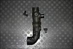
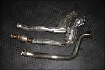 Comparison of downpipes (Top - Standard 2 1/2" MY03 non Twin Scroll, Middle - Standard 2 1/2" MY05 Twin Scroll, Bottom - ScoobySport 3" Twin Scroll).
TEST 2 - Exhaust Change - Summary of Spec
 Standard JDM Spec C MY03 Engine & Turbo
Standard Panel Filter
ScoobySport Twin Scroll De-Catted Exhaust System - 3" from turbo to backbox, no resonator, straight back box design
ECUTEK remapped ECU with basic UK Fuel map
Peak Boost - 1.50bar
Fuel - Optimax
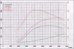
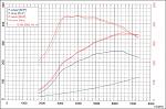
TEST 2 figure achieved was 343.5bhp @ Flywheel with 438.1Nm (323.08 lb ft) torque
TEST 2 - Exhaust Change - Comments
TEST 2 +25.3bhp +22.05lbft (peak) over Base Line
Top line figures were very impressive, especially considering these related to just an exhaust change. Even more impressive was the fact that the base line figures were from the latest MY05 standard exhaust system, so it could be assumed that had the base line been taken from the original MY03 standard exhaust system the difference (over standard) would of been even greater.
Of course top line figures do not tell the whole story, and comparing the above power graph showing the base line & TEST 2 figures on the same printout, the increases over the entire rev range are excellent.
Between 3k rpm and 4k rpm (mid-range punch) in places on the power curve, TEST 2 gave circa +40bhp & circa +50lbft over the base line. The is in the key driveability area with this exhaust resulting in a major improvement, but while also giving better top end power as well.
Overall the results showed that this specific non restrictive exhaust design, utilising a 3" bore evidently worked well to produce an extremely impressive result.
TEST 2 - Exhaust Change - Summary of Spec
Standard Panel Filter
ScoobySport Twin Scroll De-Catted Exhaust System - 3" from turbo to backbox, no resonator, straight back box design
ECUTEK remapped ECU with basic UK Fuel map
Peak Boost - 1.50bar
Fuel - Optimax
TEST 2 figure achieved was 343.5bhp @ Flywheel with 438.1Nm (323.08 lb ft) torque
TEST 2 - Exhaust Change - Comments
TEST 2 +25.3bhp +22.05lbft (peak) over Base Line
Top line figures were very impressive, especially considering these related to just an exhaust change. Even more impressive was the fact that the base line figures were from the latest MY05 standard exhaust system, so it could be assumed that had the base line been taken from the original MY03 standard exhaust system the difference (over standard) would of been even greater.
Of course top line figures do not tell the whole story, and comparing the above power graph showing the base line & TEST 2 figures on the same printout, the increases over the entire rev range are excellent.
Between 3k rpm and 4k rpm (mid-range punch) in places on the power curve, TEST 2 gave circa +40bhp & circa +50lbft over the base line. The is in the key driveability area with this exhaust resulting in a major improvement, but while also giving better top end power as well.
Overall the results showed that this specific non restrictive exhaust design, utilising a 3" bore evidently worked well to produce an extremely impressive result.
Last edited by ex-webby; Jan 27, 2007 at 02:47 PM.
Trending Topics
Thread Starter
Orange Club
Joined: Oct 1998
Posts: 13,763
Likes: 1
TEST 2 - Exhaust Change - Road Test
The first thing that hints at this exhaust systems performance is the exhaust note. Bearing in mind this is a Twin Scroll/Equal Length Header set-up, this engine has taken on a life of it's own via the exhaust note. Due to the fact that this specific exhaust system has no resonator it really does howl while on load! Subaru's previously known for their flat four burble, but changed and variably muted by the TS/ELH design, could now be mistaken for a race car with this specification of exhaust. Of course should someone opt for either a catted version and/or a resonator section, this can be muted..... but of course the choice would be yours (dependant on how sedate or extreme you wished to take your daily driver, sound wise).
Fortunately it was'nt all about improved exhaust note......
Upon driving with this exhaust on, it was evident that a slight edge had been taken off the initial on-boost feel around the 3k rpm mark (in reality smoothing out the delivery). With the Base Line configuration, the car felt like it had a kick up the backside at around this rpm, but now that almost on/off switch was muted and the power was so much more progressive but instant. Quite hard to explain in words to be honest, but definately different. Normally you find that moving from an on/off switch to progressive can make things seem slower, but not in this case. You certainly feel that huge increase in torque, which see's you surging forward. It doesnt just stop there, because as you gain rev's the power just keeps coming and coming. This did'nt seem right, especially since TEST 2 was still seeing the boost drop from 1.3bar to 1bar between 5.5-8k rpm. The pull even towards the redline was greatly improved over standard, which made a mockery of the fact that the boost was tailing off after 5.5k rpm.
So, not only was the mid-range increase and top end increase felt on the road, but also the peak boost (1.50bar) was achieved much earlier than with the Base Line configuration. Peak boost was seen some 400rpm earlier.
In all honesty, I was very surprised at how much difference an exhaust system made to this car. While I expected some increases, I certainly did not realise they would be this much by replacing the exhaust system.
Thread Starter
Orange Club
Joined: Oct 1998
Posts: 13,763
Likes: 1
TEST 3 - As Per TEST2 plus Changed Panel Filter - Overview
Since we were happy with the exhaust side of things, it was now time to look at the induction side. The best starting point was to utilise the standard airbox, but to upgrade the fillament.
The standard air fillament is made out of a paper type material, and it was thought that a less restrictive type would be more beneficial. Not only are these easy to change, but they are also very cost effective. The specific filter tested was of the K&N variety.
 This sepcific air filter is designed to achieve high, unrestricted air flow while maintaining filtration levels critical to ensure long engine life. The high flow cotton gauze air filter is washable, reusable and built to last for the life of the engine. The filters consist of four to six sheets of cotton gauze layered between two sheets of aluminum wire mesh. This media is then pleated and oiled to enhance its filtering capabilities and overall performance. The result is an air filter that allows dramatically more air into an engine, is washable and reusable. These filters are pre-oiled to save any messing around once bought.
As the filter is a direct replacement for the original, fitment is a 5 minute job. Just quickly unclip the retaining clips on top of the air box lid, and simply remove the air filter replacing it with the K&N one.
Will just a replacement panel filter make any difference�.. let�s find out.
Since we were happy with the exhaust side of things, it was now time to look at the induction side. The best starting point was to utilise the standard airbox, but to upgrade the fillament.
The standard air fillament is made out of a paper type material, and it was thought that a less restrictive type would be more beneficial. Not only are these easy to change, but they are also very cost effective. The specific filter tested was of the K&N variety.
As the filter is a direct replacement for the original, fitment is a 5 minute job. Just quickly unclip the retaining clips on top of the air box lid, and simply remove the air filter replacing it with the K&N one.
Will just a replacement panel filter make any difference�.. let�s find out.
Last edited by ex-webby; Jan 27, 2007 at 02:55 PM.
Thread Starter
Orange Club
Joined: Oct 1998
Posts: 13,763
Likes: 1
TEST 3 – As Per TEST2 plus Changed Panel Filter - Summary of Spec
 Standard JDM Spec C MY03 Engine & Turbo
K&N Panel Filter
ScoobySport Twin Scroll De-Catted Exhaust System - 3" from turbo to backbox, no resonator, straight back box design
ECUTEK remapped ECU with basic UK Fuel map
Peak Boost - 1.50bar
Fuel - Optimax
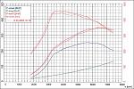
(Graph shows TEST3 Vs TEST2)
TEST 3 figure achieved was 352.3bhp @ Flywheel with 441.1Nm (325.4 lb ft) torque
TEST 3 – As Per TEST2 plus Changed Panel Filter – Comments
TEST 3 +34.1bhp +24.37lbft (peak) over Base Line
TEST 3 + 8.8bhp + 2.32lbft (peak) over TEST2
First off, we managed to push past 350bhp without any modification specific re-mapping and while still only using Optimax.
Top line figures increased for bhp quite significantly, while the increase in torque was fairly negligible.
Looking at the graph (which overlays TEST2 against TEST3 figures) shows a some what more meaningful comparison though.
As you can see, early on in the rev range (up to 3200rpm), the power saw increases of circa 10bhp and torque increases of 15lbft together with a stable increase (against TEST2) again in both power and torque above 4000rpm to past 7000 rpm. Again, this further underlines the fact that peak figures do not tell the whole story and with these kinds of increases (especially low down and higher in the rev range), the results were very pleasing from such a simple modification.
Overall the results showed that this specific uprated panel filter worked well to produce an impressive result.
Please note: No changes were made to the mapping from the Base Line. AFR’s remained virtually the same (certainly within tolerances) and boost levels remained constant and were controlled.
K&N Panel Filter
ScoobySport Twin Scroll De-Catted Exhaust System - 3" from turbo to backbox, no resonator, straight back box design
ECUTEK remapped ECU with basic UK Fuel map
Peak Boost - 1.50bar
Fuel - Optimax
(Graph shows TEST3 Vs TEST2)
TEST 3 figure achieved was 352.3bhp @ Flywheel with 441.1Nm (325.4 lb ft) torque
TEST 3 – As Per TEST2 plus Changed Panel Filter – Comments
TEST 3 +34.1bhp +24.37lbft (peak) over Base Line
TEST 3 + 8.8bhp + 2.32lbft (peak) over TEST2
First off, we managed to push past 350bhp without any modification specific re-mapping and while still only using Optimax.
Top line figures increased for bhp quite significantly, while the increase in torque was fairly negligible.
Looking at the graph (which overlays TEST2 against TEST3 figures) shows a some what more meaningful comparison though.
As you can see, early on in the rev range (up to 3200rpm), the power saw increases of circa 10bhp and torque increases of 15lbft together with a stable increase (against TEST2) again in both power and torque above 4000rpm to past 7000 rpm. Again, this further underlines the fact that peak figures do not tell the whole story and with these kinds of increases (especially low down and higher in the rev range), the results were very pleasing from such a simple modification.
Overall the results showed that this specific uprated panel filter worked well to produce an impressive result.
Please note: No changes were made to the mapping from the Base Line. AFR’s remained virtually the same (certainly within tolerances) and boost levels remained constant and were controlled.
Last edited by ex-webby; Jan 28, 2007 at 04:42 PM.
Thread Starter
Orange Club
Joined: Oct 1998
Posts: 13,763
Likes: 1
TEST 3 – As Per TEST2 plus Changed Panel Filter – Road Test
Unlike TEST2, no surprises were to be had with any increase or change in noise. As the original airbox was still retained, any induction noise was kept to a bare minimum due to the original enclosed box.
Upon road testing, it was clearly evident that slightly more response and sharpness had returned low down. Looking back at the graph, it denoted that torque was increased during spool up which was certainly related on the road to a crisper feel.
Again as TEST2, spool up was quicker, by reaching full boost (1.50 bar) at 2600rpm, some 100rpm earlier than TEST2 and now 500rpm earlier than Base Line.
Let’s be honest, both rolling road tests and road tests certainly seem to be heading in the right direction.
The bigger surprise came after 4500rpm to the redline. Even though the graph shows increases in this range for both power and torque, on the road it pulled and reved much better….. more than the rolling road figures would suggest. Again, even though the boost was still not being held above 6000rpm (dropping from 1.3bar to 1bar between 6-8k rpm), I couldn’t tell of any decernible drop in power (in fact the bhp actually levels quite nicely on all graphs) and again after TEST3 the top end had the edge over TEST2.
As TEST2, I was very surprised at the overall difference this simple modification made. Perhaps I shouldn’t of been as many simple, taken for granted and well chosen modifications can deliver what they are supposed to.
Last edited by ex-webby; Jan 28, 2007 at 04:43 PM.
Thread Starter
Orange Club
Joined: Oct 1998
Posts: 13,763
Likes: 1
TEST 4 - As Per TEST2 plus Cone Induction Kit - Overview
Ok…. Having tested a replacement panel, it was agreed that an induction kit should be tested to compare.
This would require removal of the standard airbox (while still keeping the original ducting for the airbox in place). A simple job to do, so certainly worth while.
The item to test was the Roger Clark Motorsport induction kit.
Roger Clark Motorsport have developed their own high performance induction kit for the New Age Impreza, claiming greater unrestricted air flow and improved engine response.
This induction kit consists of a high grade aluminium trumpet which is finished in a tough silver powder coating. This kit utilizes the standard air flow sensor and K&N filter element. The cotton filter element stands 220mm high with a 160mm diameter mounting flange and a stainless steel clamping ring.
Fitment of this kit is straight forward. Simply replace the standard air box assembly and then refit with this induction kit.
TEST 4 - As Per TEST2 plus Cone Induction Kit (standard sized MAF pipe) - Summary of Spec
 Standard JDM Spec C MY03 Engine & Turbo
RCM Induction Kit (standard MAF pipe)
ScoobySport Twin Scroll De-Catted Exhaust System - 3" from turbo to backbox, no resonator, straight back box design
ECUTEK remapped ECU with basic UK Fuel map
Peak Boost - 1.50bar
Fuel - Optimax
(Graph shows TEST4 Vs TEST2)
TEST 4 figure achieved was 347.2bhp @ Flywheel with 453.2Nm (334.2 lb ft) torque
Ok…. Having tested a replacement panel, it was agreed that an induction kit should be tested to compare.
This would require removal of the standard airbox (while still keeping the original ducting for the airbox in place). A simple job to do, so certainly worth while.
The item to test was the Roger Clark Motorsport induction kit.
Roger Clark Motorsport have developed their own high performance induction kit for the New Age Impreza, claiming greater unrestricted air flow and improved engine response.
This induction kit consists of a high grade aluminium trumpet which is finished in a tough silver powder coating. This kit utilizes the standard air flow sensor and K&N filter element. The cotton filter element stands 220mm high with a 160mm diameter mounting flange and a stainless steel clamping ring.
Fitment of this kit is straight forward. Simply replace the standard air box assembly and then refit with this induction kit.
TEST 4 - As Per TEST2 plus Cone Induction Kit (standard sized MAF pipe) - Summary of Spec
RCM Induction Kit (standard MAF pipe)
ScoobySport Twin Scroll De-Catted Exhaust System - 3" from turbo to backbox, no resonator, straight back box design
ECUTEK remapped ECU with basic UK Fuel map
Peak Boost - 1.50bar
Fuel - Optimax
(Graph shows TEST4 Vs TEST2)
TEST 4 figure achieved was 347.2bhp @ Flywheel with 453.2Nm (334.2 lb ft) torque
Last edited by ex-webby; Jan 28, 2007 at 04:47 PM.
Thread Starter
Orange Club
Joined: Oct 1998
Posts: 13,763
Likes: 1
TEST 4 – As Per TEST2 plus Cone Induction Kit (standard sized MAF pipe) – Comments
TEST 4 +29.0bhp +33.17lbft (peak) over Base Line
TEST 4 - 5.1bhp + 8.80lbft (peak) over TEST3
The first thing noted during the power run was fairly audible surge from using the Induction Kit. But since at this level of testing, we were only looking at bolt on mod’s without re-mapping required or further investigation, we ignored this at the time (for purposes of a power graph for comparison). Obviously surge is not a good thing, but this would be looked in to in a later test.
As shown, peak BHP figures dropped while peak torque figures increased. However, between 3400-5800k rpm both BHP and Torque saw increases over TEST3.
Looking at the graph (which overlays TEST4 against TEST3 and TEST2 figures) shows a some what more meaningful comparison though.
Although quite difficult to follow in the above power graph, the difference in low down power/torque is quite noticeable, with the standard air box and K&N filter showing the better low down power, followed by the standard air box and standard filter, with finally the induction kit showing the worse comparison out of the 3 induction modifications so far. Granted, the mid range power has shown increases with the induction kit, but the higher rev range (6000k+) has not, which was very interesting.
In summary, the induction kit lost up to 20bhp/29.5lbft up to 3200rpm, but gained up to 10bhp/14.75lbft between 3200-4600rpm over the standard air box and K&N panel filter.
As a bolt on mod, it was concluded that the standard air box with the K&N filter was the better compromise in reality, so the car was reverted back to the standard air box and the K&N filter until we ventured with specific mapping for modifications.
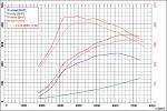
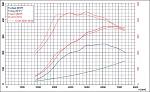
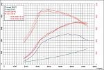 As a full comparison (even though quite hard to distinguish in this overlay), the Power Graph to the right shows the difference between all THREE induction modifications with the ScoobySport 3" Exhaust.
The earlier torque and power curve is the K&N panel filter. The next torque and power curve is the standard air filter, while the later torque and power curve is the RCM Induction Kit.
Please note: No changes were made to the mapping from the Base Line. AFR’s remained virtually the same (certainly within tolerances) and boost levels remained constant and were controlled.
TEST 4 – As Per TEST2 plus Cone Induction Kit (standard sized MAF pipe) – Road Test
Please note: No road testing was completed for TEST4.
TEST 4 +29.0bhp +33.17lbft (peak) over Base Line
TEST 4 - 5.1bhp + 8.80lbft (peak) over TEST3
The first thing noted during the power run was fairly audible surge from using the Induction Kit. But since at this level of testing, we were only looking at bolt on mod’s without re-mapping required or further investigation, we ignored this at the time (for purposes of a power graph for comparison). Obviously surge is not a good thing, but this would be looked in to in a later test.
As shown, peak BHP figures dropped while peak torque figures increased. However, between 3400-5800k rpm both BHP and Torque saw increases over TEST3.
Looking at the graph (which overlays TEST4 against TEST3 and TEST2 figures) shows a some what more meaningful comparison though.
Although quite difficult to follow in the above power graph, the difference in low down power/torque is quite noticeable, with the standard air box and K&N filter showing the better low down power, followed by the standard air box and standard filter, with finally the induction kit showing the worse comparison out of the 3 induction modifications so far. Granted, the mid range power has shown increases with the induction kit, but the higher rev range (6000k+) has not, which was very interesting.
In summary, the induction kit lost up to 20bhp/29.5lbft up to 3200rpm, but gained up to 10bhp/14.75lbft between 3200-4600rpm over the standard air box and K&N panel filter.
As a bolt on mod, it was concluded that the standard air box with the K&N filter was the better compromise in reality, so the car was reverted back to the standard air box and the K&N filter until we ventured with specific mapping for modifications.
The earlier torque and power curve is the K&N panel filter. The next torque and power curve is the standard air filter, while the later torque and power curve is the RCM Induction Kit.
Please note: No changes were made to the mapping from the Base Line. AFR’s remained virtually the same (certainly within tolerances) and boost levels remained constant and were controlled.
TEST 4 – As Per TEST2 plus Cone Induction Kit (standard sized MAF pipe) – Road Test
Please note: No road testing was completed for TEST4.
Last edited by ex-webby; Jan 28, 2007 at 04:47 PM.
Thread Starter
Orange Club
Joined: Oct 1998
Posts: 13,763
Likes: 1
TEST 5 – As Per TEST2 plus Cone Induction Kit (80mm sized MAF pipe), Replacement Inlet, 3 port Boost Controller & remapping- Overview
At the end of TEST4 we had now come to the stage where we wanted to start to remap the car, to gain the best benefit of each modification (if applicable). All previous tests were completed without altering the map as it was from the Base Line.
The best reason to start this now, was because we wanted to test the larger 80mm MAF pipe version of the RCM Induction Kit, along with a non restrictive inlet pipe and a different boost controller.
Induction Kit
As per TEST4, but with a slightly bigger MAF pipe (80mm)
Induction Kit, showing cone and trumpet (trumpet shows space for MAF sensor)
Non-Restrictive Inlet
Is the standard Inlet Pipe (after Induction or Air Box to Turbo) restrictive? One of the perceived thoughts would be to get as much unrestricted air in as possible, to gain more power.....only one way to find out.
Unfortunately to see the standard inlet pipe in it's entirety is pretty much impossible by just looking at it in situ. The only real way is by removing it completely which is a bit of a task. Because of this we were slightly hesitant to try this modification, only from the "What happens if it makes things worse and we have to revert back to the standard inlet pipe" scenario. Usually the logical way would be to remove the intake manifold (as many spur's from the inlet pipe take place under the manifold - on a STi this is the red mass of cast pipe work on top of the engine), which is very time consuming. Luckily Powerstation have mastered an easier approach, but unfortunately this requires the inlet pipe coming off to be cut in a couple of places. Not ideal for testing (in case the original had to be refitted), but for speediness it was the way forward.
Last edited by ex-webby; Jan 28, 2007 at 04:47 PM.
Thread Starter
Orange Club
Joined: Oct 1998
Posts: 13,763
Likes: 1
Removal/Fitment of Induction Kit and New Inlet Pipe (and comparisons)
Since both of these items are being fitted at the same time a whole multitude of items need to be fully removed.
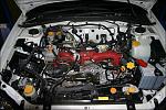 The removal of the front strut brace, top mount intercooler, airbox lid, short elbow between airbox lid and inlet pipe (inlet pipe is the large black pipe underneath the left hand side of the manifold) and cold air feed that directs cold air from the front of the bonnet to the inner wing.
 The complete removal of the airbox, giving space for the Induction Kit. You will notice that the inner wing section is still present. This will stay in place, for fitment of the normal cold air feed ducting at the end.
To remove the inlet pipe (even by using the easier method) requires removal of the alternator and surrounding bracketry.
 The inlet pipe requires a connection on the top of the rear and front right side to be removed. The best way for this is to use an axe saw blade. For obvious reason (because of other piping in this area) extreme caution must be made not to sever any other pipework.
 Once all connecting pipes on the original inlet pipe have been either disconnected or removed, the standard inlet pipe can be pulled through from the turbo.
 The standard inlet as in it's natural position, from a top view perspective. As you can see the pipe from the top (exploded to the left) and pipe from the lower right (exploded to the right) has been cut. This was required to remove the standard inlet pipe insitu.
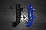 The comparison of the standard inlet pipe (left) and non-retrictive inlet pipe (right). As you can see the non-restrictive pipe is much smoother in it's deisgn (both pipe diameters on entry and exit are the same). Special note is that the non-restrictive deisgn does not have a corrugated centre piece.
Since the non-restrictive inlet pipe is much more flexible than the rigid hard plastic standard inlet pipe, the fitment of the new pipe was straight forward. Please not the non-restrictive pipe has an extra take off (centre of pipe, towards entry), these needs to be blocked off for this application.
Since both of these items are being fitted at the same time a whole multitude of items need to be fully removed.
To remove the inlet pipe (even by using the easier method) requires removal of the alternator and surrounding bracketry.
Since the non-restrictive inlet pipe is much more flexible than the rigid hard plastic standard inlet pipe, the fitment of the new pipe was straight forward. Please not the non-restrictive pipe has an extra take off (centre of pipe, towards entry), these needs to be blocked off for this application.
Last edited by ex-webby; Jan 28, 2007 at 04:47 PM.
Thread Starter
Orange Club
Joined: Oct 1998
Posts: 13,763
Likes: 1
To fit the induction kit, requires a reducer elbow fitting, which takes the 80mm down to the standard 68mm of the inlet pipe, replacing the standard elbow.
TEST 5 – As Per TEST2 plus Cone Induction Kit (80mm sized MAF pipe), Replacement Inlet & remapping - Summary of Spec
RCM Induction Kit (Large – 80mm - MAF pipe)
Non-Restrictive replacement Inlet Pipe
ScoobySport Twin Scroll De-Catted Exhaust System - 3" from turbo to backbox, no resonator, straight back box design
ECUTEK remapped ECU modified from basic UK Fuel map
Peak Boost - 1.4bar
Fuel - Optimax
(Graph shows TEST5)
TEST 5 figure achieved was 360.0bhp @ Flywheel with 424.7Nm (313.2 lb ft) torque
Last edited by ex-webby; Jan 28, 2007 at 04:48 PM.
Thread Starter
Orange Club
Joined: Oct 1998
Posts: 13,763
Likes: 1
TEST 5 – As Per TEST2 plus Cone Induction Kit (80mm sized MAF pipe), Replacement Inlet & remapping – Comments
TEST 5 +41.8bhp +12.17lbft (peak) over Base Line
TEST 5 +12.8bhp –21.00lbft (peak) over TEST4
Good news first…… we achieved 360bhp!!!!! Unfortunately that was the only real good news, as it was evident that this latest batch of modifications caused some severe problems with surge (or what certainly seemed like it).
TEST4 had previously highlighted this issue but now it was even more evident, so further investigation was required.
The surge appeared between approximately 3000-4000 rpm and from 4000 rpm onwards it disappeared. This was both extremely audiable from both inside and outside the car, which sounded very similar to you trying to breath in through your mouth nearly closed and then quickly moving your tongue backwards and forwards from the opening (sounds weird, but gives the same audio effect). While looking at the boost gauge as the car was being run on the rolling road, it showed the boost very rapidly fluctuating around the boost target through this same rev range and then settling from approximately 4000 rpm onwards.
So what was causing it?!?!
As previously mentioned, the RCM Induction Kit even with the standard sized MAF pipe caused similar issues, so it was a fair bet that it was something around the induction kit. Perhaps with this 80mm MAF pipe together with the non restrictive inlet pipe making it even worse. Whether or not it was worse was a side issue….. the important thing was trying to find out how to eradicate it.
Surge is not a good thing to have, as not only does it not sound very good, it hampers the boost stabilisation and can have a detrimental effect on Turbo life.
For background information, Surge is caused by the inability for the engine to consume the air produced by the Turbo at a given point. Normally (obviously dependant on amount of air and at what rpm the Surge happens) the engine can consume the increased air further up the rev range, as the engines cams and valve usage increases allowing more air to be consumed. When Surge occurs, the Turbo compressor produces more air than the engine can consume, which causes a backup of air at the intake which actually creates reverse-flowing pressure waves that can be very damaging to the turbo.
Last edited by ex-webby; Jan 28, 2007 at 04:48 PM.
Thread Starter
Orange Club
Joined: Oct 1998
Posts: 13,763
Likes: 1
The immediate conclusion was that the increased diameter MAF pipe and non restrictive inlet pipe had allowed for a bigger increase in airflow, based on the reasons why Surge happens. The same conclusion could then be derived from TEST4, even though the Surge was not as bad it was still apparent and was obviously caused by increased airflow, even though it was still the standard MAF pipe size (68mm) and standard inlet pipe.
The only way we would allow the car to run, was to try and decrease or eliminate the Surge. Although perhaps seemingly meaningless, we decided to try and map around this issue, rather than taking specific parts back off as it was important to try and learn more form the current issues. The only way around this was to cap the boost between 3000-4000 rpm to approximately 1bar, with normal previous boost targets from thereafter.
Upon running the car on the rolling road the Surge was greatly reduced, but still slightly apparent. As with any testing, we were prepared to leave the slight Surge issue to see what effects the whole of this issue had on both the car itself while being run in normal road conditions.
Now that you know what was experienced, it will hopefully help to explain the power graph shown for TEST5 above.
As you can see the power and torque pick up is very steady up to 5000 rpm, which relates to the boost targets being lower than previous up to and just beyond 4000 rpm. To be perfectly honest, we all thought the Power Graph looked like a Naturally Aspirated cars power delivery. Again because of the boost targets being lower initially, peak torque was made extremely high (5055rpm) compared to previous runs of around 3900rpm�. very progressive indeed.
Since very little of the map (apart from boost targets up to approximately 4000 rpm and appropriate MAF rescaling because of the larger MAF pipe) was actually changed, it was good to see a pick up of power and torque in the higher rev range over previous TEST�s (hence the increased peak power figure), which is still very impressive for such modifications.
While the TEST did not provide as many plus points (and certainly more negative ones) that previous tests had shown, it did at least show us that more power was available, but also was an eye opener on how critical air flow restrictions are based on the standard turbo used in this application.
Powerstation did comment on the fact that while the Induction Kit was very well made and designed, it was not conducive for this application and remit. This was mainly down to the surge issue and would be certainly something that would be retested with a bigger turbo (Stage 2).
Thread Starter
Orange Club
Joined: Oct 1998
Posts: 13,763
Likes: 1
TEST 5 – As Per TEST2 plus Cone Induction Kit (80mm sized MAF pipe), Replacement Inlet & remapping – Road Test
Pretty much everything concluded from the Rolling Road runs, made for identical and expected comparison on the road.
Power delivery was very progressive and had no immediate rush of Torque early on. Boost reached 1bar between 3000 - 4000 rpm but rose to 1.4bar very soon after and then started to tail off as before soon after 6000 rpm. The car really went very well in the higher rev range, especially from 6k onwards. Not very good for road use as you may appreciate.
Surge was still evident with both the noise and also fluctuation of the boost gauge between the 3-4k rpm rev range, but it was no where near as bad prior to reducing the boost targets between the same rev range.
As also expected, Induction “Roar” was also evident, but somewhat muted by the louder Surge noise.
Another interesting point that no Power Graph can show, was the increase in inlet temps at the MAF with an engine bay Induction Kit. Since the Road Testing at any stage was over several days (and not just a quick blast up the road), temperatures were monitored (as were general driving characteristics). During this specific Road Test period is was found that under previous similar ambient temperatures (between TEST3 and TEST5), inlet temperatures had raised by nearly 20degC in cases (with ALL cases showing increases of at least 10degC over that of the air box). Under these same situations the car certainly did not feel as sharp as before (under the same conditions), but then when ambient temperatures had decreased it certainly felt better.
I have read on many occasions that Induction Kits do not cause higher inlet temps (or if they do, they are negligible) while the vehicle is moving with normal airflow. Unfortunately, the monitoring of temperatures has proved this to not be correct with the standard inlet ducting that was being used.
Regardless of efficiencies elsewhere, increased inlet temperatures are not good and will only help to kerb potential power and responsiveness. Boost attained was also hampered during the higher inlet temperature peaks, more so than seen with the Standard Air box.
Realistically we have taken a backward step in a way with this latest set of modifications, but all results and learning are good and at least this has shown issues with such modifications. Now we need to try and rectify the issue and find a way forward.
Last edited by ex-webby; Jan 28, 2007 at 04:48 PM.
Thread Starter
Orange Club
Joined: Oct 1998
Posts: 13,763
Likes: 1
TEST 6 – As Per TEST5 plus remapping- Overview
Before physically changing items, it was decided that further investigation would be completed on the mapping side of things to see if we could map the surge out, but obviously not to the point of reducing boost by the amount that had previously been seen in TEST5.
Expanding on the previous reasons why Surge takes place, thoughts were made concerning possibly trying to get the engine to deal with increased air in the rev range of 3-4k rpm. Two main areas for investigation would be cam timing and ignition. These areas would be looked at and altered (if required) via the ECUTEK software.
TEST 6 – As Per TEST5 plus remapping- Summary of Spec
 Standard JDM Spec C MY03 Engine & Turbo
RCM Induction Kit (Large – 80mm - MAF pipe)
Non-Restrictive replacement Inlet Pipe
ScoobySport Twin Scroll De-Catted Exhaust System - 3" from turbo to backbox, no resonator, straight back box design
ECUTEK remapped ECU modified from basic UK Fuel map
Peak Boost - 1.50bar
Fuel - Optimax
(Graph shows TEST6 Vs TEST3)
TEST 6 figure achieved was 359.4bhp @ Flywheel with 446.9Nm (329.57 lb ft) torque
Before physically changing items, it was decided that further investigation would be completed on the mapping side of things to see if we could map the surge out, but obviously not to the point of reducing boost by the amount that had previously been seen in TEST5.
Expanding on the previous reasons why Surge takes place, thoughts were made concerning possibly trying to get the engine to deal with increased air in the rev range of 3-4k rpm. Two main areas for investigation would be cam timing and ignition. These areas would be looked at and altered (if required) via the ECUTEK software.
TEST 6 – As Per TEST5 plus remapping- Summary of Spec
RCM Induction Kit (Large – 80mm - MAF pipe)
Non-Restrictive replacement Inlet Pipe
ScoobySport Twin Scroll De-Catted Exhaust System - 3" from turbo to backbox, no resonator, straight back box design
ECUTEK remapped ECU modified from basic UK Fuel map
Peak Boost - 1.50bar
Fuel - Optimax
(Graph shows TEST6 Vs TEST3)
TEST 6 figure achieved was 359.4bhp @ Flywheel with 446.9Nm (329.57 lb ft) torque
Last edited by ex-webby; Jan 28, 2007 at 04:49 PM.
Thread Starter
Orange Club
Joined: Oct 1998
Posts: 13,763
Likes: 1
TEST 6 – As Per TEST5 plus remapping- Comments
TEST 6 +41.2bhp +28.54lbft (peak) over Base Line
TEST 6 - 00.6bhp +16.37lbft (peak) over TEST5
First off, no matter what we did we could not eliminate the Surge in it’s entirety. It was reduced, but not eliminated and certainly not reduced enough to be acceptable.
Again, to try and reduce the Surge (as well as any ignition and cam timing adjustments) boost targets were profiled slightly differently, but were increased back to previous targets.
Peak figures for Torque were now getting back up, so at least adjustments that had been made were positive ones.
Looking at the Power Graph above, the comparison shows some negative and some positive results. Since the Graph achieved during TEST3 was deemed to be the best overall result and certainly proved to be the best on-road result so far, it made sense to use that as a comparison.
What jumps out is the decrease in BHP and Torque during TEST6 against TEST3 up to 3600 rpm. Resulting in up to 30bhp and 50lbft decreases in places. However, on the positive side increases can be seen from 4800 rpm through past 7000 rpm. Resulting in up to 13bhp and 15lbft increases in places.
Conclusions drawn from this test highlighted that investigation now needed to be made around the Induction Kit and replacement Inlet pipe.
Last edited by ex-webby; Jan 28, 2007 at 04:49 PM.
Thread Starter
Orange Club
Joined: Oct 1998
Posts: 13,763
Likes: 1
TEST 6 – As Per TEST5 plus remapping- Road Test
As with TEST5 Surge was still audible and boost was pulsating through the same rev range as before, although now it was not as bad.
Bottom end response was certainly better than TEST5, but still felt very fluffy and hesitant due to the presence of Surge.
Top end pull was as TEST5, still being very strong.
Temperatures at the MAF were still as TEST6, so as previously any feedback on comparisons with power delivery and feel were taken from cooler conditions (as higher Inlet Temperatures caused sharpness to be reduced somewhat).
From the investigation so far, the ideal would be the low down response of TEST3, coupled with the increased top end pull of TEST5 & TEST6.
If anything, this test has shown what the extra breathing capabilities of the induction kit allows for and this test will certainly help with Stage 2 (even if it wasn't giving the required results for Stage 1).
Last edited by ex-webby; Jan 28, 2007 at 04:49 PM.
Thread Starter
Orange Club
Joined: Oct 1998
Posts: 13,763
Likes: 1
TEST 7 – As Per TEST6 plus Standard Airbox with K&N Panel Filter and remapping- Overview
Couple of steps forward and one step back was the order of the day for this test.
Since the elimination of Surge could not be completed via just remapping alone, we decided to now take specific modifications off to try and isolate what caused the Surge.
The easiest way forward was at first to replace the RCM Induction Kit with the Standard Airbox with the K&N Panel Filter, since this has proved very good in a previous test without the problems of Surge.
Due to the fact of changing MAF pipe sizes, from the RCM 80mm version back to the standard 68mm version, rescaling of the MAF was required within the ECUTEK software. At the same time, the boost targets and ignition were all reverted back to what they were for TEST3 to aid comparisons.
TEST 7 – As Per TEST6 plus Standard Airbox with K&N Panel Filter and remapping - Summary of Spec
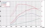 Standard JDM Spec C MY03 Engine & Turbo
K&N Panel Filter
Non-Restrictive replacement Inlet Pipe
ScoobySport Twin Scroll De-Catted Exhaust System - 3" from turbo to backbox, no resonator, straight back box design
ECUTEK remapped ECU modified from basic UK Fuel map
Peak Boost - 1.50bar
Fuel - Optimax
(Graph shows TEST7 Vs TEST3)
TEST 7 figure achieved was 358.0bhp @ Flywheel with 442.5Nm (326.33 lb ft) torque
Couple of steps forward and one step back was the order of the day for this test.
Since the elimination of Surge could not be completed via just remapping alone, we decided to now take specific modifications off to try and isolate what caused the Surge.
The easiest way forward was at first to replace the RCM Induction Kit with the Standard Airbox with the K&N Panel Filter, since this has proved very good in a previous test without the problems of Surge.
Due to the fact of changing MAF pipe sizes, from the RCM 80mm version back to the standard 68mm version, rescaling of the MAF was required within the ECUTEK software. At the same time, the boost targets and ignition were all reverted back to what they were for TEST3 to aid comparisons.
TEST 7 – As Per TEST6 plus Standard Airbox with K&N Panel Filter and remapping - Summary of Spec
K&N Panel Filter
Non-Restrictive replacement Inlet Pipe
ScoobySport Twin Scroll De-Catted Exhaust System - 3" from turbo to backbox, no resonator, straight back box design
ECUTEK remapped ECU modified from basic UK Fuel map
Peak Boost - 1.50bar
Fuel - Optimax
(Graph shows TEST7 Vs TEST3)
TEST 7 figure achieved was 358.0bhp @ Flywheel with 442.5Nm (326.33 lb ft) torque
Last edited by ex-webby; Jan 28, 2007 at 04:49 PM.
Thread Starter
Orange Club
Joined: Oct 1998
Posts: 13,763
Likes: 1
TEST 7 – As Per TEST6 plus Standard Airbox with K&N Panel Filter and remapping - Comments
TEST 7 +39.8bhp +25.30lbft (peak) over Base Line
TEST 7 - 1.4bhp - 3.25lbft (peak) over TEST6
Since remapping had took place at this stage we had managed to push the peak BHP to just under 360bhp!!!! Which on such simply and cost effective mods was extremely good (especially on only Optimax fuel).
Upon the first run on the rolling road with the standard airbox now back on, all Surge had now fully disappeared!
Looking at the Power Graph above, comparing TEST7 against TEST3 with the only difference now being the non-restrictive replacement Inlet Pipe, again the first area that draws attention is up to 3400 rpm. As with TEST6, something is still hampering low down BHP and Torque compared to the previous TEST3. However (as seen between TEST3 & TEST4), just changing from the RCM Induction Kit back to the Standard Airbox with K&N Panel Filter has improved this slightly.
The only logical conclusion that can be drawn from this (from deduction of what is different), is the fact that the non-restrictive replacement Inlet Pipe is causing this issue low down. From deduction and logical "Physics" knowledge the standard Inlet Pipe design is probably specific to increase air flow speed (which may be through the fact that the standard Inlet Pipe has a corrugated centre, which one would assume causes some form of restriction). Theory is theory, but without appropriate testing this can not concluded.
The only way to conclude that the non-restrictive replacement Inlet Pipe was causing this issue low down, would be to replace it with the Standard Inlet Pipe. After much thought it was decided that due to planned modifications for Stage 2, together with the time it would take to complete this task (unlike the method used in TEST5, to revert back would certainly require the removal of the Intake Manifold) that we would leave the Inlet Pipe as it was.
Looking at the rest of the Power Graph, subtle increases can be seen in the power band for both BHP and Torque from 4800 rpm onwards. Unfortunately the delivery looks quite “lumpy”, which was probably due to the fact that heat was starting to have an effect (since by this time, several runs had been made and inlet temps were 29degsC). However, it does point out that (would the run had been smoother) that some more power was being gained higher up in the rev range compared to TEST3.
Bearing the last paragraph in mind, it is not an easy statement to say that should you undergo these types of modifications that the non-restrictive replacement Inlet Pipe should not be considered. Personal suggestion would be to not replace it as a matter of course, but to see how power is delivered and maintained without it in the first instance.
Last edited by ex-webby; Jan 28, 2007 at 04:49 PM.
Thread Starter
Orange Club
Joined: Oct 1998
Posts: 13,763
Likes: 1
TEST 7 – As Per TEST6 plus Standard Airbox with K&N Panel Filter and remapping - Road Test
As concluded with the Rolling Road tests, Surge had now completely disappeared on the road as well.
Power delivery and responsiveness was felt like it was back to levels attained on previous tests (even though comparisons over previous runs would indicate the lowdown issue). To be perfectly honest the car felt very quick. Unfortunately since it had been over 2 months after the work completed for TEST3, it was unpractical to give any kind of concrete comparison as regards to “feel”. The difference between what was now, and what was before with TEST6 was like chalk and cheese. The car pulled much stronger from low down, but pulled just as well further up.
Monitoring the temperatures again, it was immediately evident that changing back to the Standard Air box had dramatically reduced the Inlet Temperatures measured at the MAF. As a direct example, travelling to Powerstation in the morning to run through TEST7 (while still being at TEST6 stage) the Inlet Temperatures were between 40-42degC. Leaving Powerstation late afternoon with TEST7 onboard, the Inlet Temperatures were 26-28degC. The ambient temperatures in the morning were in fact lower than what they were in the afternoon!
Upon further continued road driving over another week, the car certainly felt more responsive even during ambient temperatures that reached 30degC, compared to similar conditions with the previously installed Induction Kit. Boost was also more stable, with more consistant peaked boost and better held boost relational to targets.
Following on from what we had concluded so far, we would stick with the Standard Air box with K&N Panel Filter, as the overall driveability and benefits far outweighed any positive finds of using an in engine bay Induction Kit.
Last edited by ex-webby; Jan 28, 2007 at 04:50 PM.
Thread Starter
Orange Club
Joined: Oct 1998
Posts: 13,763
Likes: 1
TEST 8 – As Per TEST7 plus Uprated Actuator, 3 Port Boost Solenoid and remapping- Overview
Since we had found an agreed base platform of mod's during TEST7, we decided to further build on this and try some other minor mod's with more mapping to extract more.
While looking at getting more from increased ignition, boost was also a favourite to increase.
Since held boost up to this point was a slight problem (not reaching targets) in different gears, coupled with the thoughts of increasing overall targets slightly, it was decided that we would look at replacing and testing uprated "boost controlling" hardware from the standard equipment. The specific areas that would be looked at would be wastegate actuators and electronic boost control valves.
Wastegate Actuator
The wastegate actuator controls the opening and closing (to a degree) of the wastgate, which in turn dictates how much boost the turbo will try and make (boost dependant on turbo specification).
An actuator works by pressure generated by the engine, pushing the actuator rod out (when exceeding specific pressure) closing the wastegate and retracting (after forward movement) when pressure is dropped, opening the wastegate.
An actuator is normally rated with a "crack" pressure, which dictates what pressure is required to move the actuator rod out to close the wastegate and reduce boost. The higher the "crack" pressure, the more boost the turbo will create while the actuator is in rest.
Pressure to the actuator is normally fed via a boost control valve (explained later). This pressure can then be "bleed off" via the boost control valve, to create a scenario where in fact the actuator will let the turbo produce more boost than the "crack" pressure dictates. While this is a way to produce more boost, to actually hold boost pressure for a specific period of time it may be required to use a actuator with a higher "crack" pressure in any case to sustain this. This normally requires an actuator with a harder spring.
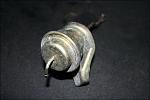 Since we wanted to experiment with holding a higher defined boost target, we decided to upgrade the standard actuator (shown right) with one that had a stiffer spring (higher "crack" pressure) and
 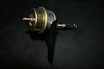 adjustable rod for changing pre-load on the wastegate.
Since we had found an agreed base platform of mod's during TEST7, we decided to further build on this and try some other minor mod's with more mapping to extract more.
While looking at getting more from increased ignition, boost was also a favourite to increase.
Since held boost up to this point was a slight problem (not reaching targets) in different gears, coupled with the thoughts of increasing overall targets slightly, it was decided that we would look at replacing and testing uprated "boost controlling" hardware from the standard equipment. The specific areas that would be looked at would be wastegate actuators and electronic boost control valves.
Wastegate Actuator
The wastegate actuator controls the opening and closing (to a degree) of the wastgate, which in turn dictates how much boost the turbo will try and make (boost dependant on turbo specification).
An actuator works by pressure generated by the engine, pushing the actuator rod out (when exceeding specific pressure) closing the wastegate and retracting (after forward movement) when pressure is dropped, opening the wastegate.
An actuator is normally rated with a "crack" pressure, which dictates what pressure is required to move the actuator rod out to close the wastegate and reduce boost. The higher the "crack" pressure, the more boost the turbo will create while the actuator is in rest.
Pressure to the actuator is normally fed via a boost control valve (explained later). This pressure can then be "bleed off" via the boost control valve, to create a scenario where in fact the actuator will let the turbo produce more boost than the "crack" pressure dictates. While this is a way to produce more boost, to actually hold boost pressure for a specific period of time it may be required to use a actuator with a higher "crack" pressure in any case to sustain this. This normally requires an actuator with a harder spring.
Last edited by ex-webby; Jan 28, 2007 at 04:50 PM.
Thread Starter
Orange Club
Joined: Oct 1998
Posts: 13,763
Likes: 1
Boost Solenoid
What a clever box of tricks this can be!
The boost solenoid (boost controller) controls the flow of pressure to the actuator, which in turn controls the opening and closing of the wastegate (to a degree) to ultimately control what boost the turbo will produce.
Since (in this case) the standard ECU via ECUTEK actually has the parameters for what boost should be acheived at what rpm etc, this ultimately controls the hardware (in this case the boost solenoid) by supplying an electrical current from the ECU which opens and closes the solenoid to allow the low pressure from the turbo to feed the actuator.
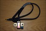 The standard boost solenoid (2 port - shown right) is quite slow reacting, which can be fine in certain circumstances, but when you wish to achieve finer and more accurate control of boost (say for instance in an overboost scenario) you would need a faster reacting boost
 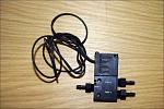 solenoid. Because of further experimentation we decided to install a 3 port boost solenoid (shown right), which would allow us to bleed off pressure if required to assist in finite boost control.
What a clever box of tricks this can be!
The boost solenoid (boost controller) controls the flow of pressure to the actuator, which in turn controls the opening and closing of the wastegate (to a degree) to ultimately control what boost the turbo will produce.
Since (in this case) the standard ECU via ECUTEK actually has the parameters for what boost should be acheived at what rpm etc, this ultimately controls the hardware (in this case the boost solenoid) by supplying an electrical current from the ECU which opens and closes the solenoid to allow the low pressure from the turbo to feed the actuator.
Last edited by ex-webby; Jan 28, 2007 at 04:50 PM.
Thread Starter
Orange Club
Joined: Oct 1998
Posts: 13,763
Likes: 1
TEST 8 – As Per TEST7 plus Uprated Actuator, 3 Port Boost Solenoid and remapping - Summary of Spec
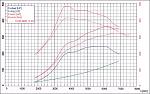 Standard JDM Spec C MY03 Engine & Turbo
K&N Panel Filter
Non-Restrictive replacement Inlet Pipe
ScoobySport Twin Scroll De-Catted Exhaust System - 3" from turbo to backbox, no resonator, straight back box design
ECUTEK remapped ECU modified from basic UK Fuel map
Uprated Actuator
3 Port Boost Solenoid
Peak Boost - 1.6bar
Fuel - Optimax
(Graph shows TEST8 Vs TEST1)
TEST 8 figure achieved was 361.1bhp @ Flywheel with 483.1Nm (356.27 lb ft) torque
TEST 8 – As Per TEST6 plus Standard Airbox with K&N Panel Filter and remapping - Comments
TEST 8 +42.9bhp +55.67lbft (peak) over Base Line
TEST 8 + 3.1bhp +29.94lbft (peak) over TEST7
Again we had still achieved over 360bhp, but on top of that we had managed to bring the Torque up to over 355lbft!!!
With a combination of the stronger actuator and also the quicker reacting boost solenoid, we were able to allow for a bit of safe over boost (seen on the graph by the peak torque curve), which should make an effective mid range surge on the road. By having a stronger actuator and increasing the duty cycle of the boost solenoid, it is possible to induce over boost…. Which when allowed for and within acceptable parameters, coupled with a faster reacting boost solenoid is quite acceptable (the faster reacting 3 port boost solenoid, will bleed off air quicker – than a standard 2 port solenoid - to reduce attained boost – which if more than target boost will be classed as over boost - back to target boost).
Further investigation of the graph also shows that as well as the increased peak torque, the sustained torque after peak until 5000rpm was again increased from TEST7…. Again this should prove interesting in the mid range on the road.
Power curves between TEST7 and TEST8 show no real changes.
The other noticeable point is the sudden drop in power and torque around the 6200rpm and onwards range. While we had experimented with dialing in more ignition from 6000rpm onwards, it was concluded that intake temps had perhaps caused this dip power (Intake Temps were measured at 31degs for this specific run).
Last edited by ex-webby; Jan 28, 2007 at 04:50 PM.
Thread Starter
Orange Club
Joined: Oct 1998
Posts: 13,763
Likes: 1
TEST 8 – As Per TEST6 plus Standard Airbox with K&N Panel Filter and remapping – Road Test
What a difference!!
Mid range punch was excellent, with the added (controlled) over boost and stronger torque in the mid range the car felt so much stronger.
Interestingly the power in the higher range didn’t drop off on the road (as regards to the area around the dip, 6200rpm onwards), so it would seem perfectly acceptable that the dip on the Dyno readout was due to rising inlet temps on that day.
Because adjustments had been made to ingear compensators, the car was also more responsive in every gear. Boost climbed faster and reached peak better (2nd, 3rd and 4th).
Overall the car was getting very fast now on the road now, and being at a stage that all concerned were very happy with the results from what could be classed as very basic mod’s (although the trick was finding a working combination, with the mapping skills to match), we started to ask ourselves if anymore could be achieved.
Taking in to account that we had reached a very impressive level of power and performance, while still running on straight Optimax with no signs of DET and the ECU running with no ignition retard at any load sites, further testing was tempting. Primarily, the inlet pipe saga was at the fore front of our minds…. Mmmmm.
Last edited by ex-webby; Jan 28, 2007 at 04:50 PM.
Thread Starter
Orange Club
Joined: Oct 1998
Posts: 13,763
Likes: 1
TEST 9 – As Per TEST8 plus Standard Inlet Pipe – Overview
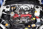 “After much thought it was decided that due to planned modifications for Stage 2, together with the time it would take to complete this task (unlike the method used in TEST5, to revert back would certainly require the removal of the Intake
 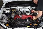 Manifold) that we would leave the Inlet Pipe as it was”. It’s strange….. when we decided the above I had a suspicious feeling we may return to it (as we have already found out, nothing is ever THAT simple)! So here we are……it was to be a
 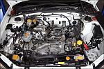 fairly time consuming job, but we just had to find out whether or not there was any differences back to back between the standard inlet and an aftermarket one (which would be deemed as being giving better performance).... only one way to find out!
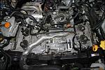 As previously discussed, to be able to remove the existing silicon hose and replace it with the original inlet hose would require removal of the manifold. While the job is not specifically hard, it does require time.
Removal of Manifold to replace silicon inlet pipe with standard inlet pipe
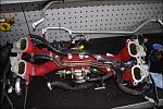 So off with the new and on with the old. The reason why the removal of the manifold is required to change back to the original inlet pipe, is because the original pipe is very stiff and will not bend (to get underneath the manifold and on to the
 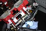 pipe connections) like the silicon one did previously.
Removal of Manifold to replace silicon inlet pipe with standard inlet pipe
Last edited by ex-webby; Jan 28, 2007 at 05:17 PM.