
Blow through maf - finally sorted..


Well, its been a long time coming...
But to cut a long story short - i have spent a fair bit of time modifying my car and trying to get it to run great. Everything was going good until i got the fmic and 05/06 20G combo. Now dont get me wrong, the hybrid gt fmic is amazing for the price, and the 20G also is great bang for buck. But put them together on a maf system and hello lift off judder!!
It got to the point of driving me crazy! crusing down the motorway, slight boost in 4th, ease off the throttle and duh duh duh duh (car shakes).. awful. Anyway, after trying many combinations of no dump valve, hot side dump valve, adjustable, vta, etc etc they all pretty much made no difference at all. There was only one solution.
enter... Blow through MAF.
The idea of measuring how much air ACTUALLY is about to enter the throttle body always appealed to me. But the question was - how to do it? No tuner that i know of could supply me a blow through pipe to mount my maf onto.. Plus i didnt really want to use the standard my99/00 maf anyway.
After a little while searching i finally managed to get myself a pukka Q45 maf. thanks to jay M A for supplying it - much appreciated. But that was after being robbed on good old eb*y buying some fake q45 copy!!
but, sometimes things work out for the best in the most unusual of ways. It suddenly came to me one day, why not use the orginal maf tube and housing that the Q45 is already sitting in? Well thats exactly what i did. The only problem i had, was the side of the air flow meter casing that has the connection for the air box, or apexi filter. In the end, i took a saw and hacked off the end of the duff Q45 to make myself a maf adaptor, thus giving me a 90mm o/d tube at either end. take a look at the pic, you will see what i mean.
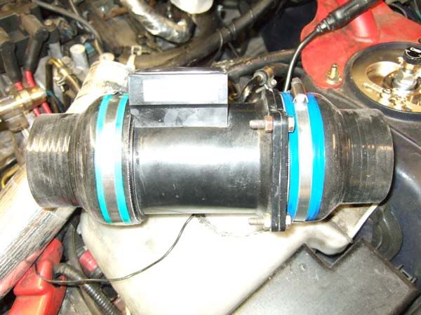
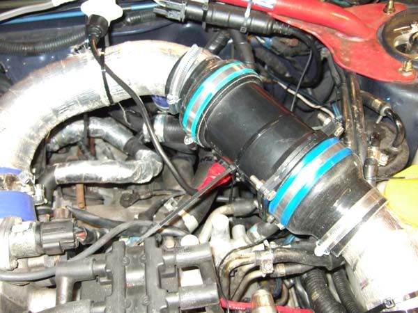
AS you can see, with the aid of two silicone reducer pipes ( which again i could not get hold of in this country for a reasonable price - ended up @ 6 quid each from the us of a! ) of size 3.5" to 2.5" the 90mm o/d maf tube can be connected upto the hard pipe of the hybrid gt fmic. take a look at the following pics to see how i placed it.
Tube section cut away
maf in place and all jubilee'd in
The only problem i have at the moment is the casing of the maf tube is a little high. i really need to get some fuel hose and run the fuel hose from the fuel filter over the pipe. i think this would cure the problem.
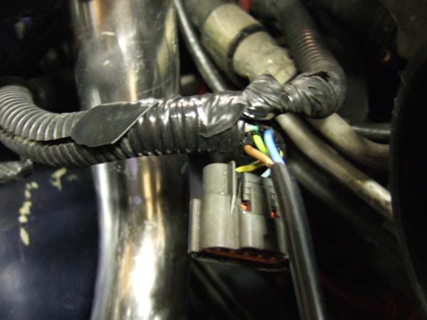
The wiring was pretty straight forward, there are only 3 wires for the Q45 - power, signal and ground. I ended up using a kettle type socket to connect the maf to the loom of the car. it was so i could disconnect it if i needed to in the future. The original my99 maf connector still exists on the loom in case i ever need to go back to using a "suck through" maf!! - but i doubt that!
Having no idea how the maf curve of the Q45 would relate to the my99 maf curve, i decided to start the car and see how things progressed. After a little tweak to the Maf curve using my datalogit and powerfc i had the car idling at a decent 14.5:1 afr. excellent. Now came the worrying time of actually going for a drive!! Equiped with the laptop and all necessary gear i got to the point of running around 1.3 bar in second gear with a very crude fuel and ignition map to get me started. Its all i had time for this eveing but results look promising.
At 1.3 bar in second gear, around 6000 rpm the maf voltage is reading 4.52v
- It works!!!
Admittedly, i will need to spend hours on the map to get the car running how i had it before but i think it shouldnt take too long.
I guess its not such a huge project as such, but very significant in terms of maf troubles. I certainly dont see the need to move over to a mafless system quite just yet
If there is any interest in this, i can follow up this thread with my mapping and how the car comes together. if anyone needs any info on wiring or where i bought parts from then that would be no problems either.
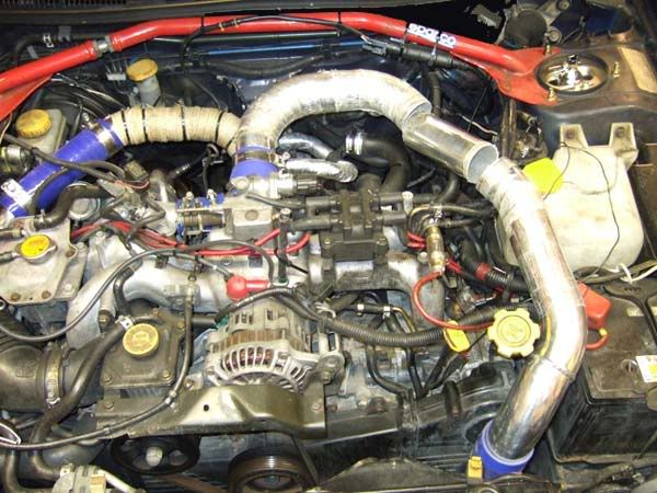
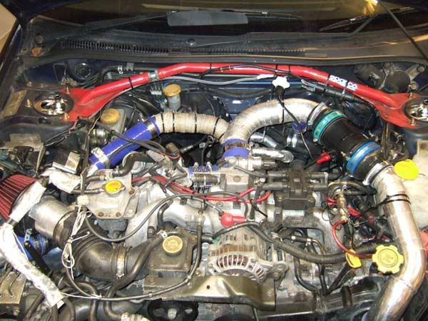
Here's a full engine bay shot to finish off with

But to cut a long story short - i have spent a fair bit of time modifying my car and trying to get it to run great. Everything was going good until i got the fmic and 05/06 20G combo. Now dont get me wrong, the hybrid gt fmic is amazing for the price, and the 20G also is great bang for buck. But put them together on a maf system and hello lift off judder!!
It got to the point of driving me crazy! crusing down the motorway, slight boost in 4th, ease off the throttle and duh duh duh duh (car shakes).. awful. Anyway, after trying many combinations of no dump valve, hot side dump valve, adjustable, vta, etc etc they all pretty much made no difference at all. There was only one solution.
enter... Blow through MAF.
The idea of measuring how much air ACTUALLY is about to enter the throttle body always appealed to me. But the question was - how to do it? No tuner that i know of could supply me a blow through pipe to mount my maf onto.. Plus i didnt really want to use the standard my99/00 maf anyway.
After a little while searching i finally managed to get myself a pukka Q45 maf. thanks to jay M A for supplying it - much appreciated. But that was after being robbed on good old eb*y buying some fake q45 copy!!
but, sometimes things work out for the best in the most unusual of ways. It suddenly came to me one day, why not use the orginal maf tube and housing that the Q45 is already sitting in? Well thats exactly what i did. The only problem i had, was the side of the air flow meter casing that has the connection for the air box, or apexi filter. In the end, i took a saw and hacked off the end of the duff Q45 to make myself a maf adaptor, thus giving me a 90mm o/d tube at either end. take a look at the pic, you will see what i mean.
AS you can see, with the aid of two silicone reducer pipes ( which again i could not get hold of in this country for a reasonable price - ended up @ 6 quid each from the us of a! ) of size 3.5" to 2.5" the 90mm o/d maf tube can be connected upto the hard pipe of the hybrid gt fmic. take a look at the following pics to see how i placed it.
Tube section cut away
maf in place and all jubilee'd in
The only problem i have at the moment is the casing of the maf tube is a little high. i really need to get some fuel hose and run the fuel hose from the fuel filter over the pipe. i think this would cure the problem.
The wiring was pretty straight forward, there are only 3 wires for the Q45 - power, signal and ground. I ended up using a kettle type socket to connect the maf to the loom of the car. it was so i could disconnect it if i needed to in the future. The original my99 maf connector still exists on the loom in case i ever need to go back to using a "suck through" maf!! - but i doubt that!
Having no idea how the maf curve of the Q45 would relate to the my99 maf curve, i decided to start the car and see how things progressed. After a little tweak to the Maf curve using my datalogit and powerfc i had the car idling at a decent 14.5:1 afr. excellent. Now came the worrying time of actually going for a drive!! Equiped with the laptop and all necessary gear i got to the point of running around 1.3 bar in second gear with a very crude fuel and ignition map to get me started. Its all i had time for this eveing but results look promising.
At 1.3 bar in second gear, around 6000 rpm the maf voltage is reading 4.52v
- It works!!!
Admittedly, i will need to spend hours on the map to get the car running how i had it before but i think it shouldnt take too long.
I guess its not such a huge project as such, but very significant in terms of maf troubles. I certainly dont see the need to move over to a mafless system quite just yet
If there is any interest in this, i can follow up this thread with my mapping and how the car comes together. if anyone needs any info on wiring or where i bought parts from then that would be no problems either.
Here's a full engine bay shot to finish off with
Scooby Regular
iTrader: (2)
Joined: May 2000
Posts: 8,626
Likes: 1
From: Class record holder at Pembrey Llandow Goodwood MIRA Hethel Blyton Curborough Lydden and Snetterton
Wow great stuff, glad the MAF is working OK, didn't know it could do blowthrough otherwise I wouldn't have sold it !
I've got a newage STI one ready to go in the same location, so I'll actively keep an eye on this thread to see how you get on
I've got a newage STI one ready to go in the same location, so I'll actively keep an eye on this thread to see how you get on


Joined: Nov 2003
Posts: 13,356
Likes: 58
From: in the woods...........555 Wagon Sqn
I'd be very interested in seeing how the mapping goes, I only have an 18g but still suffer from lift off judder and it would be great to cure it cheaply
Hi Jay, the maf is great, much appreciated that you sold it me!
The lift off judder has completely disapeared. Although its funny that i still drive the car the way i used to by snapping shut the throttle instead of gradually lifting off.
I'll work on the map during the rest of the week and get the car back upto 1.45 - 1.5 bar again. I will get some datalogit graphs up showing how the blow through is coping and what effects i notice (if any) + maf voltages etc.


Trending Topics
Joined: Nov 2003
Posts: 13,356
Likes: 58
From: in the woods...........555 Wagon Sqn


thanks for kind words everyone. just got back from some more map tweaking. The power is starting to come back now  1.35 bar in 2nd gear held to redline but still need more fuel adjustments as running 10.45 afr which is too rich. a little more ignition and less fuel on partial boost and i'll be getting there.
its such a joy to drive on the motorway now too, much more relaxing.
should be on for a few graphs tomorrow and i may also fit my dump valve back on the hot side of the fmic! being a blow through, dump valves are no problem now. Im running without one at the moment but the noise from a vta -less system is very harsh imo. The air kind of grates over the turbo on lift off!
1.35 bar in 2nd gear held to redline but still need more fuel adjustments as running 10.45 afr which is too rich. a little more ignition and less fuel on partial boost and i'll be getting there. its such a joy to drive on the motorway now too, much more relaxing.
should be on for a few graphs tomorrow and i may also fit my dump valve back on the hot side of the fmic! being a blow through, dump valves are no problem now. Im running without one at the moment but the noise from a vta -less system is very harsh imo. The air kind of grates over the turbo on lift off!
Scooby Regular
iTrader: (2)
Joined: May 2000
Posts: 8,626
Likes: 1
From: Class record holder at Pembrey Llandow Goodwood MIRA Hethel Blyton Curborough Lydden and Snetterton
On the FMIC pipework it looks like the DV takeoff is after the MAF, I've been told on a blowthrough it needs to be before the MAF? I am going to cut and shut pipe, swapping the bend with the DV takeoff with the bend at the top of the cam covers.
And of course I'm going to have to dramatically reassess my opinion on VTA DV's
And of course I'm going to have to dramatically reassess my opinion on VTA DV's
Hey AL99, glad it's all working as expected. I have been planning to go down this route for a while now ... and your and Neils experiences have only confirmed this as a good decision. Thanks for sharing and let us know how the mapping comes along.
Thanks for sharing and let us know how the mapping comes along.
Jay m a, you're absolutely right! The dump valve take off on mine is blocked off, any dump valve should be run with enough pipework "before" the maf so as not to interfere with air flows.
A couple of posts up i said i plan to run a vta, i have a silicone adaptor for the hot side of the fmic pipework. its fits where the two hard pipes connect under the apexi filter, I'll take some pics later to show you.
A couple of posts up i said i plan to run a vta, i have a silicone adaptor for the hot side of the fmic pipework. its fits where the two hard pipes connect under the apexi filter, I'll take some pics later to show you.
Joined: Nov 2003
Posts: 13,356
Likes: 58
From: in the woods...........555 Wagon Sqn

Scooby Regular
Joined: Sep 2008
Posts: 128
Likes: 0
From: Werrington born, Walsall bred
As mentioned, a blow-thru maf system would be ideal if the VTA dump valve fitted before the MAF rather than between the MAF and throttle body. That way no metered air escapes the system, which should make throttle lift-off and re-application even better.
Just a thought.
Wonder why non of the big tuners have ever come up with this on their mainstream FMIC conversions? (except for going MAF-less, cough, cop out LOL )
Second advantage is temperature compensation, MAF at the thottle body will compensate for heated/intercooled air charge which is different in temperature to the air temp found at the intake filter. So in theory, fueling should be more accurate.
Just a thought.
Wonder why non of the big tuners have ever come up with this on their mainstream FMIC conversions? (except for going MAF-less, cough, cop out LOL
)Second advantage is temperature compensation, MAF at the thottle body will compensate for heated/intercooled air charge which is different in temperature to the air temp found at the intake filter. So in theory, fueling should be more accurate.
Last edited by Wenker Man; Nov 7, 2008 at 11:10 AM.
This is a snippet of a datalogit graph showing a 2nd gear pull. With the fuel now at around 11:1 afr on full boost its feeling much better. Boost is just dipping slightly at around 5800 rpm. still need some work on 3rd gear..and as for 4th.. anyone got a dyno i could borrow for an hour ?? 
its a big picture and im not quite sure how its going to come out? - clicky on it for full res.

its a big picture and im not quite sure how its going to come out? - clicky on it for full res.
drop your tools!...
im not convinced. Yes it does cure lift off judder, yes its much smoother to drive on the motorway. yes it does measure REAL air that flows in to the throttle body....but, i just cant determine what is causing spurious readings that i keep getting.
For no apparent reason, and not necessarily under big boost i sometimes get jumps in air flow readings. i mean big jumps. and they can be under or over readings.
Air leak? - possibly, under heavy boost there may be some air escaping the two plastic housings where they are joined. Plastic is never going to replace aluminimium in this circumstance.
Vibration? - almost certainly it will be vibrating, but the effect would be unkown.
Air flow characteristics? - maybe at some air flow velocity i am getting a swirl effect in the reducer, stab in the dark i know but if its not understood and ruled out then its a possibility.
Heat - the plastic housings after a long drive around get very hot, -expansion? maybe this is causing the air leak above?
I think the fact is, this "way" of measuring air does work. but it needs much more dedicated hardware in turns of properly made aluminium parts. As it stands, im returning the setup to the original suck through.
which sucks!
how much was the simtek by the way?..
Joined: Nov 2003
Posts: 13,356
Likes: 58
From: in the woods...........555 Wagon Sqn
drop your tools!...
im not convinced. Yes it does cure lift off judder, yes its much smoother to drive on the motorway. yes it does measure REAL air that flows in to the throttle body....but, i just cant determine what is causing spurious readings that i keep getting.
For no apparent reason, and not necessarily under big boost i sometimes get jumps in air flow readings. i mean big jumps. and they can be under or over readings.
Air leak? - possibly, under heavy boost there may be some air escaping the two plastic housings where they are joined. Plastic is never going to replace aluminimium in this circumstance.
Vibration? - almost certainly it will be vibrating, but the effect would be unkown.
Air flow characteristics? - maybe at some air flow velocity i am getting a swirl effect in the reducer, stab in the dark i know but if its not understood and ruled out then its a possibility.
Heat - the plastic housings after a long drive around get very hot, -expansion? maybe this is causing the air leak above?
I think the fact is, this "way" of measuring air does work. but it needs much more dedicated hardware in turns of properly made aluminium parts. As it stands, im returning the setup to the original suck through.
which sucks!
how much was the simtek by the way?..
im not convinced. Yes it does cure lift off judder, yes its much smoother to drive on the motorway. yes it does measure REAL air that flows in to the throttle body....but, i just cant determine what is causing spurious readings that i keep getting.
For no apparent reason, and not necessarily under big boost i sometimes get jumps in air flow readings. i mean big jumps. and they can be under or over readings.
Air leak? - possibly, under heavy boost there may be some air escaping the two plastic housings where they are joined. Plastic is never going to replace aluminimium in this circumstance.
Vibration? - almost certainly it will be vibrating, but the effect would be unkown.
Air flow characteristics? - maybe at some air flow velocity i am getting a swirl effect in the reducer, stab in the dark i know but if its not understood and ruled out then its a possibility.
Heat - the plastic housings after a long drive around get very hot, -expansion? maybe this is causing the air leak above?
I think the fact is, this "way" of measuring air does work. but it needs much more dedicated hardware in turns of properly made aluminium parts. As it stands, im returning the setup to the original suck through.
which sucks!
how much was the simtek by the way?..
great update, shame it hasn't worked out the way you planned after so much work  Simtek for me too next for what it's worth.

Scooby Regular
Joined: Jul 2000
Posts: 2,209
Likes: 0
From: Lancashire
Have you logged these? Do they occur at steady state or only during TPS or MAP transients?
Andrew...
After removing the flow meter last night, to my amazement it was wet inside?
Now obviously this was causing the terrible readings i was seeing last night and the weather was awful, it was lashing it down. But im 99% sure the meter was sealed and air tight so i honestly have no idea where the water was being pulled in? maybe water resting on the top was being sucked in through the smallest of gaps, or the hoses were bulging under boost. who knows?
Now, this explains last nights readings (i was logging but never saved as i was concentrating on low load fuelling ) . The other day, i had a similar problem - in fact i nearly hit the windscreen!! I DO have this logged and Airflow voltage is fine, boost is fine(1.2bar iir ish), but AFR jumps from 11.x to 14.5! - BUT - i was running very low on fuel - Fuel Surge?? it would be the first time i felt it and it wasnt nice. Now, it was raining on this night also but because i never removed the flow meter i dont know if it was water contamination again or not. no knock readings on this either.
They didnt occur at steady state. It was normally under acceleration. I had already comensated for TPS accel values so it wasnt this. What was visible though, was map load points would vary. So lets say for example, 3rd gear, 1.3 bar, 4000 rpm normally sits at map position P16. Well sometimes it would shoot down to P19 even P20, so it was over reading significantly. (evaporation of water on the airflow element? )
thinking about this it would'nt suprise me if all the problems were water related, as the first night i tried this ( the log and pic above in 2nd gear ) it was dry and i had no problems at all. It made me feel confident to put my foot down and get stuck into the mapping.
If i could figure out where the water was entering then it might be worth another try. I really do want to nail this way of measuring airflow, be it with dedicated aluminium parts or through my own mock up.
What i might do is purchase some proper mikalor clamps and try again. This time thinking of any possible entry for water. I could also house the meter in some kind of plastic shroud to protect from rain water entering through the scoop and from underneath.
any ideas from anyone welcome..
Scooby Regular
Joined: Jul 2000
Posts: 2,209
Likes: 0
From: Lancashire
I've never had problems like that with a blow through, however, water passing over the hot wire element could cause what you are seeing.
Is there any way water could get into your airfilter? Any cold air feeds or scoop?
Don't use Mikalor clamps, waste of money, decent quality solid band s/s 'jubilee' clip are fine.
Andrew...
Is there any way water could get into your airfilter? Any cold air feeds or scoop?
Don't use Mikalor clamps, waste of money, decent quality solid band s/s 'jubilee' clip are fine.
Andrew...
no cold air scoop or air feeds..
The water was however only in the maf tube and the tube to the throttle body. I could not see any evidence of water from the fmic pipe that runs up past the cam cover. So assuming it wasnt "sucked in" where could it have got through?
do you know if the Q45 mafs are susceptible to positive pressure? In terms of how the maf element is concealed within the tube? (air leakages etc)
I know the my99 mafs are slightly different in design and such look like they would be more resilient to being pressurized as the maf is screwed into the tube and appears to be more "sealed in" if you see what i mean? The Q45 looks as though its not quite so sealed where the metering section enters the tube.. sorry if im not explaining that very well.
I'll bear that in mind about the mikalors. I do use the solid jubilees in some areas and they have been fine.
I think that maybe a plastic rain gaurd may be a good addition to the blowthrough. It would give it some protection to water falling onto it. any water inside then would have to have been sucked in through the filter.
I might just give that a try this evening as it only takes 5 mins to swap over and the map can just load straight on. I may also double check on the seal between the maf tube and maf adaptor tube.
its back on again..
i hate defeat.
This time with better clamps on the silicone hose. Also a better gasket between the maf tube and self made adaptor.
Results last night looked promising. Steady values and good results upto 1.3 bar. BUT - it was'nt raining.
There is however, still a flaw. After 1.4 bar i can hear a loud whistle come from the area of the engine bay the maf tube sits. Either there is a leak around the gasket/join of the maf tube or there is a fundamental maximum pressure limit the maf tube can take as it is not designed for pressure.
I have a few more ideas to seal where the tubes join - i think if the leak persists i may try the my99 maf tube as this is certainly sealed where the maf inserts into the pipe and bolts nicely with 3 hex screws.