

psi3 Help


Thread Starter
Scooby Newbie
Joined: Feb 2010
Posts: 12
Likes: 0
I'm having one heck of a time finding any info on these things...
I spent roughly 4 hours searching everywhere I could think of for any information and this site had the most available but it still didn't have what I needed.
https://www.scoobynet.com/lighting-o...ml#post8569873
Was the closest I came to finding what I was after, but my connector is only 12 pins instead of the 25.
What I'm trying to do is hook up the oil pressure and oil temperature senders to the psi3. If anyone could help me out, I would GREATLY appreciate it. No one in the states knows anything about these.
Thanks to all for your time.
Matt
*edit*
Also, I've read the manual .pdf and it doesn't have what I'm looking for. I'm looking for a pinout for connector 2.
Last edited by mkiisupraman18; Feb 28, 2010 at 08:05 PM.
Hi mate,
You don't say which model you have but these are the connections for the later VFD display units.
Only make connections with the ignition switched off and the communications connector disconnected from the vehicle.
Connector 1 is a 5 pin and connector 2 is 12 pin viewed from the back of the unit pin 1 is on the left for both connectors and pin 5 connector 1 and pin 12 on connector 2 will be on the right hand side.
PIN 1 � WARNING AND SHIFT LIGHT DRIVE
From what i remember oil pressure has 3 wires which go to pins 5, 7 ,9.I cant remember the colours on the pressure sensor though.
Oil temp goes to pins 7 & 8. Makes no difference which way round the temp wires are connected.
Hope that helps
Stu.
You don't say which model you have but these are the connections for the later VFD display units.
PSI3 GRAPHICAL ECU MONITOR EXTERNAL CONNECTIONS
FOR MODELS VGS1, VGS2, VGS3, VGS3, VGS4, VGS5, VGA1
DOCUMENT REVISION B
GENERAL
The ECU monitor has several additional functions that will require external connections to be made to the rear of the unit.
Please read this document in its entirety before attempting any installation.
Below is a layout of the rear external connections.
Please refer to this during any installation.
Connections are made using a removable screw terminal blocks. Ensure screw connections are tight and well insulated
from the other connections and vehicle wiring/metal parts etc. Only make connections with the ignition switched off and
the communications connector disconnected from the vehicle.
These connectors are viewed from rear of unit.
Only make connections with the ignition switched off and the communications connector disconnected from the vehicle.
Connector 1 is a 5 pin and connector 2 is 12 pin viewed from the back of the unit pin 1 is on the left for both connectors and pin 5 connector 1 and pin 12 on connector 2 will be on the right hand side.
Only make connections with the ignition switched off and the communications connector disconnected from the vehicle.
CONNECTOR 1
PIN 1 � COMMUNICATIONS (TO OBD CONNECTOR PIN 7)
PIN 2 � RX
PIN 3 � TX
PIN 4 � POWER GROUND (TO OBD CONNECTOR PIN 5)
PIN 5 � POWER POSITIVE (TO OBD CONNECTOR PIN 16)
CONNECTOR 2
CONNECTOR 1
PIN 1 � COMMUNICATIONS (TO OBD CONNECTOR PIN 7)
PIN 2 � RX
PIN 3 � TX
PIN 4 � POWER GROUND (TO OBD CONNECTOR PIN 5)
PIN 5 � POWER POSITIVE (TO OBD CONNECTOR PIN 16)
CONNECTOR 2
PIN 1 � WARNING AND SHIFT LIGHT DRIVE
PIN 2 � NC
PIN 3 � NC
PIN 4 � NC
PIN 5 � SENSORS GROUND
PIN 6 � GROUND
PIN 7 � +5V SENSORS
PIN 8 � OIL TEMP SENSOR INPUT
PIN 9 � OIL PRESSURE SENSOR INPUT
PIN 10 � BOOST SENSOR INPUT
PIN 11 � FUEL PRESSURE INPUT
PIN 12 � E.G.T. PRESSURE INPUTPIN 3 � NC
PIN 4 � NC
PIN 5 � SENSORS GROUND
PIN 6 � GROUND
PIN 7 � +5V SENSORS
PIN 8 � OIL TEMP SENSOR INPUT
PIN 9 � OIL PRESSURE SENSOR INPUT
PIN 10 � BOOST SENSOR INPUT
PIN 11 � FUEL PRESSURE INPUT
From what i remember oil pressure has 3 wires which go to pins 5, 7 ,9.I cant remember the colours on the pressure sensor though.
Oil temp goes to pins 7 & 8. Makes no difference which way round the temp wires are connected.
Hope that helps
Stu.
Thread Starter
Scooby Newbie
Joined: Feb 2010
Posts: 12
Likes: 0
Stu... if you weren't across an ocean from me, I'd hug you.
Thanks a million man. I wasn't having any luck finding anyone who knew about these.
Thanks a million man. I wasn't having any luck finding anyone who knew about these.
Last edited by mkiisupraman18; Mar 1, 2010 at 04:35 PM.
Hi,
Have you got it working now? I downloaded the connections guide from the psi3 website about 4 years ago so it is possible they changed the connections or maybe the US model is different. Unfortunately it seems psi3 are no longer trading but if you need any further help i will see if i can find any further info for you.
Stu.
Thread Starter
Scooby Newbie
Joined: Feb 2010
Posts: 12
Likes: 0
Unfortunately I haven't got it working. I've got the box itself working vie the OBDII cable, but I can't get the oil pressure or temp sensors to read. Which is what one would expect trying the wrong diagrams.
I really appreciate your help Stu.
I really appreciate your help Stu.
Hi,
I have had a look at my unit and the temp sensor is connected to pins 5 and 8 the pressure sensor is connected as follows Black wire to pin 5 Red wire to pin 7 White wire to pin 9. Are you using Defi sensors? As that is what the unit is designed to use.
Stu.
I have had a look at my unit and the temp sensor is connected to pins 5 and 8 the pressure sensor is connected as follows Black wire to pin 5 Red wire to pin 7 White wire to pin 9. Are you using Defi sensors? As that is what the unit is designed to use.
Stu.
Trending Topics
Thread Starter
Scooby Newbie
Joined: Feb 2010
Posts: 12
Likes: 0
Yes, I am using the defi sensors.
But it seems as though my pins are different from yours.
I will try hooking the wires up that way again but I was not showing voltage to any of the wires.
Do I need to tell the unit some how that it needs to be looking for the sensors or should it pick up automatically that they are hooked up?
But it seems as though my pins are different from yours.
I will try hooking the wires up that way again but I was not showing voltage to any of the wires.
Do I need to tell the unit some how that it needs to be looking for the sensors or should it pick up automatically that they are hooked up?
Hi,
Now you mention it there is a set up menu and you may need to tell the unt which sensors are connected. I know that on mine pins 5 & 6 are sensor ground connecions, so you could check that with a meter the only other thing i can do is check all the pins on mine with a meter and see if any have a voltage reading. But i can't do that till i get home tonight.
Now you mention it there is a set up menu and you may need to tell the unt which sensors are connected. I know that on mine pins 5 & 6 are sensor ground connecions, so you could check that with a meter the only other thing i can do is check all the pins on mine with a meter and see if any have a voltage reading. But i can't do that till i get home tonight.
Thread Starter
Scooby Newbie
Joined: Feb 2010
Posts: 12
Likes: 0
When I checked them with a multimeter I wasn't showing anything that was grounded, which both concerned and confused me...
Ill hook them up tonight and run through all of the menues to see if I can find a setting for them.
Ill hook them up tonight and run through all of the menues to see if I can find a setting for them.
Hi,
You do have to turn on the sensors in the set up menu. if it still doesnt work you could try checking all the pins with a meter again and post the readings or pm them to me and i will see if i can make sense of them.
Stu.
You do have to turn on the sensors in the set up menu. if it still doesnt work you could try checking all the pins with a meter again and post the readings or pm them to me and i will see if i can make sense of them.
Stu.
On mine there are 4 buttons on the right hand side press the top 1 which is labelled enter then scroll through the pages using the arrow buttons to page 4 "user options" press enter then scroll to oil temp and see if it states fitted or not fitted press enter to change status and do the same for the pressure sensor then press escape.
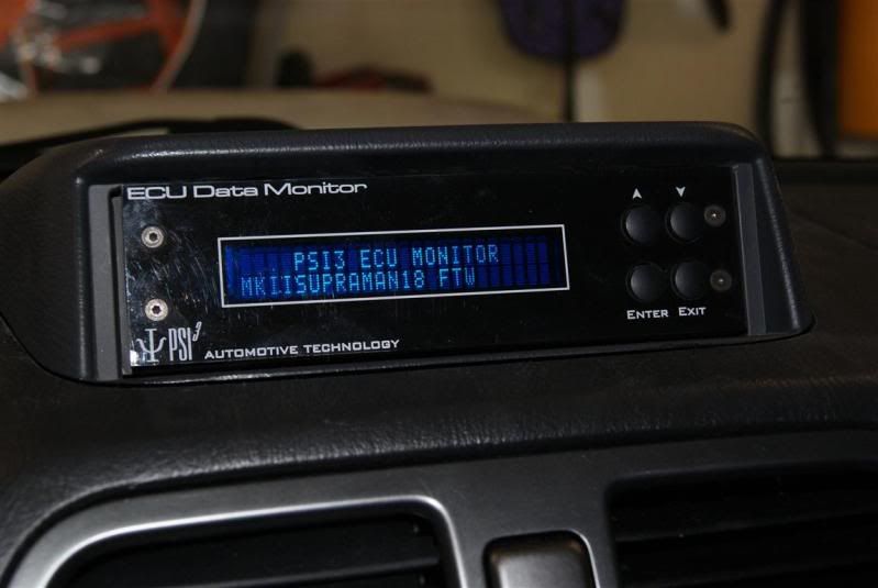
The image is of a vfd monitor is yours the same?

The image is of a vfd monitor is yours the same?

I've got some of the manuals and fitting guides for the sensors on my home email. PM me your email address and I'll get them over to you.
I'd imagine yours is a VFD one also, from the part number. So it must be Version 12 with the VFD screen. Maybe the faceplate looks different because they were custom ones about.
I'd imagine yours is a VFD one also, from the part number. So it must be Version 12 with the VFD screen. Maybe the faceplate looks different because they were custom ones about.
Thread Starter
Scooby Newbie
Joined: Feb 2010
Posts: 12
Likes: 0
I've got some of the manuals and fitting guides for the sensors on my home email. PM me your email address and I'll get them over to you.
I'd imagine yours is a VFD one also, from the part number. So it must be Version 12 with the VFD screen. Maybe the faceplate looks different because they were custom ones about.
I'd imagine yours is a VFD one also, from the part number. So it must be Version 12 with the VFD screen. Maybe the faceplate looks different because they were custom ones about.
You tried Stu, not your fault I have an older version.
Clutching at straws now is it one of these?
If not do you have a pic?
http://i3.photobucket.com/albums/y90...to/gauges2.gif
If not do you have a pic?
http://i3.photobucket.com/albums/y90...to/gauges2.gif
Thread Starter
Scooby Newbie
Joined: Feb 2010
Posts: 12
Likes: 0
Pretty sure that's it Stu.
*edit*
That's the only pic I have available, obviously the first screen showing the model number and all that would make it a bit more useful. lol
*edit*
That's the only pic I have available, obviously the first screen showing the model number and all that would make it a bit more useful. lol
Last edited by mkiisupraman18; Mar 3, 2010 at 05:46 PM.
Hi mate,
Might be getting closer now i have 1 of these buried in the garage somewhere i changed it for the later model in 2006. Anyhow here are the connections for this type of monitor.
(CONNECTOR 1)
PIN 1 - COMMUNICATIONS (TO OBD CONNECTOR PIN 7)
PIN 4 - POWER GROUND (TO OBD CONNECTOR PIN 5)
PIN 5 - POWER POSITIVE (TO OBD CONNECTOR PIN 16)
12 pin (CONNECTOR 2)
PIN 1 - WARNING AND SHIFT LIGHT POSITIVE (+12 Volts output)
PIN 2 - WARNING AND SHIFT LIGHT GROUND (-12 Volts Out)
PIN 3 - WATER INJECTION RELAY POSITIVE (+12 Volts output)
PIN 4 - WATER INJECTION RELAY GROUND (-12 Volts Out)
PIN 5 - SENSORS GROUND
PIN 6 - SENSORS +5 V
PIN 10 - OIL TEMPERATURE SENSOR INPUT
PIN 11 - OIL PRESSURE SENSOR INPUT
OIL PRESSURE CONNECTION
RED WIRE ------------- CONNECT TO CONNECTOR 2 PIN 6
WHITE WIRE ------------- CONNECT TO CONNECTOR 2 PIN 11
BLACK WIRE ------------- CONNECT TO CONNECTOR 2 PIN 5
OIL TEMPERATURE CONNECTION
RED / BLACK WIRE -------- CONNECT TO CONNECTOR 2 PIN 10
BLACK WIRE -------- CONNECT TO CONNECTOR 2 PIN 5
Hope this works, i will find the instruction manual for it at the weekend, pm me your email and i will send them to you as a pdf file.
Stu.
Thread Starter
Scooby Newbie
Joined: Feb 2010
Posts: 12
Likes: 0
^ I like it that it has the 12v on pin #1!
Can't wait to get off work to try this.
Thanks to the both of you for helping out an outsider who joined this forum for nothing more than information. This community is awesome worldwide.
I would stay and kinda lurk, but I know that EU stuff has no bearing on US stuff.
Stu, I will PM you my e-mail.
Can't wait to get off work to try this.
Thanks to the both of you for helping out an outsider who joined this forum for nothing more than information. This community is awesome worldwide.
I would stay and kinda lurk, but I know that EU stuff has no bearing on US stuff.
Stu, I will PM you my e-mail.


Thread
Thread Starter
Forum
Replies
Last Post