

My FMIC install - WIP


Thread Starter
Scooby Regular
Joined: Aug 2006
Posts: 86
Likes: 0
From: South East Africa
After my last thread on an intercooler install
(https://www.scoobynet.com/general-te...ateral-ic.html)
i realised that i wouldn't be able to get any decent kind of setup without having to cut into the bumper. So i figured what the hell, if we are going to do some cutting then let's get it done properyl..
And cut we did. This is the progress so far, let me know what you guys think and if you have any useful suggestions please feel free to add.
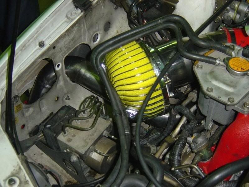
Pic of engine bay
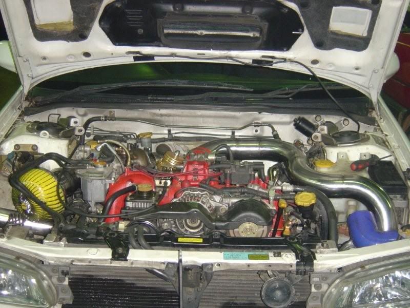
Removed the battery and now relocated to the boot. Installing water-methanol injection, the bottle will be in the boot also.
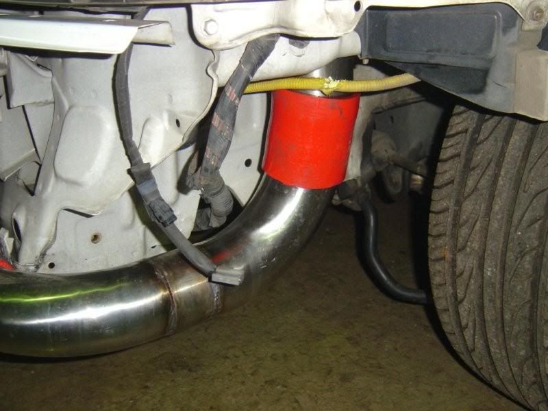
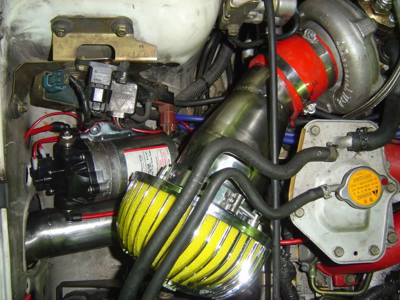
Piping at front left wheel
(wiring insulation got damaged a little bit. Will have to tape that up properly)
Piping at front right wheel
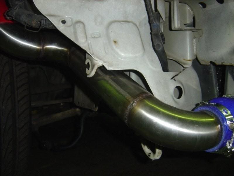
We are still going to do the finishing touches later on, such as putting rubbers round the points where the piping contacts with the body, making up joins so that the piping is easier to remove in pieces when needing to change plugs, etc.
AND WHAT INTERCOOLER, I HEAR YOU ASKING??
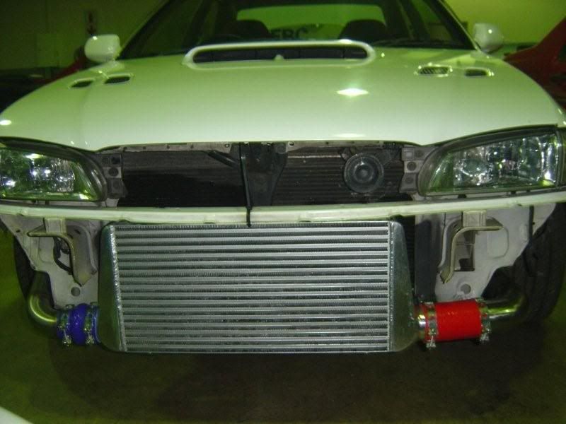
What do you guys think?
(https://www.scoobynet.com/general-te...ateral-ic.html)
i realised that i wouldn't be able to get any decent kind of setup without having to cut into the bumper. So i figured what the hell, if we are going to do some cutting then let's get it done properyl..
And cut we did. This is the progress so far, let me know what you guys think and if you have any useful suggestions please feel free to add.
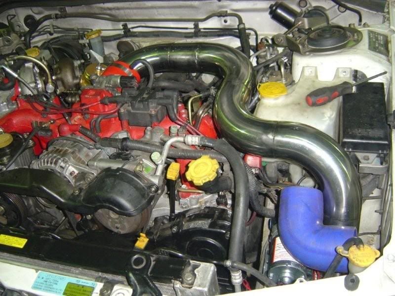
Pic of engine bay
Removed the battery and now relocated to the boot. Installing water-methanol injection, the bottle will be in the boot also.
Piping at front left wheel
(wiring insulation got damaged a little bit. Will have to tape that up properly)
Piping at front right wheel
We are still going to do the finishing touches later on, such as putting rubbers round the points where the piping contacts with the body, making up joins so that the piping is easier to remove in pieces when needing to change plugs, etc.
AND WHAT INTERCOOLER, I HEAR YOU ASKING??
What do you guys think?

Thread Starter
Scooby Regular
Joined: Aug 2006
Posts: 86
Likes: 0
From: South East Africa
yes we tried something new with the intercooler piping. I cut a hole through the bodywork where the battery tray is, and relocated the battery to the boot. I haven't seen anybody else doing this but it seemed like a good idea.
fitting the bumper on with that intercooler is proving to be a bit of a challenge. I'm having to cut into the bumper but will keep updating this thread with the progress.
was hoping for anybody with experience in piping to comment on whether the piping setup looks like it will be efficient or if they can spot any potential problems.
i'm also using a very large wastegate (for no specific reason other than i had it layng around) but this may need to be changed later.
Thread Starter
Scooby Regular
Joined: Aug 2006
Posts: 86
Likes: 0
From: South East Africa
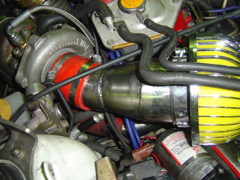
rotated turbo to try and avoid the dreaded #3 cylinder heating problems. The piping from the turbo to intercooler inlet actually runs underneath the air intake piping and then toward the front-right wing (fender as we call it). You can see a bit in the pics above.
The exhaust side is pretty straightforward with the piping just going downward and joining the exhaust system. I've removed the cat converter (obviously) and am using a Blitz exhaust.
The exhaust side is pretty straightforward with the piping just going downward and joining the exhaust system. I've removed the cat converter (obviously) and am using a Blitz exhaust.
Trending Topics

Scooby Regular
Joined: Aug 2005
Posts: 3,957
Likes: 1
From: East coast.
Well the cold side piping from intercooler to throttle body looks great. That's got to be much much better than the route on my Autobahn one which makes a tight 180 bend straight out of the IC, then a tight 90 right up behind the radiator and hot water pipes, with hardly enough room to get round. It also is very tight across alongside the battery and needed cutting and articulating there with another silicone joiner. Your pipework looks nice and big (same bore as the IC outlets?) and smoothly done as well. Do the welds look as neat on the inside as well as the outside?
Thread Starter
Scooby Regular
Joined: Aug 2006
Posts: 86
Likes: 0
From: South East Africa
yes the piping is 76mm, same as the outlets on the intercooler. The welds have been done by a specialist and very good quality. Insides look pretty similar, if not slightly better.
i looked at many many pics of the popular and existing setups, and noted that 90% of them have the 180degree bend as you described and then come up alongside the radiator.
My rad has aluminium tanks which are a bit broader than the standard, so the space between rad and cam covers are too tight to get any piping coming through there.
We thought long and hard for every other alternative as i wanted to minimise cutting the body. Eventually had a brainstorm to do it this way.
Scooby Regular
Joined: Aug 2005
Posts: 3,957
Likes: 1
From: East coast.
Yes full 3" piping is great if you can manage it like you have. Be interesting to see what kind of results you get from it. What have you done with the hot side piping from turbo to IC? How have you increased the pipe bore from the smaller compressor outlet into the 3" IC inlet?

Scooby Regular
Joined: Jun 2006
Posts: 1,568
Likes: 0
From: South West
Yes full 3" piping is great if you can manage it like you have. Be interesting to see what kind of results you get from it. What have you done with the hot side piping from turbo to IC? How have you increased the pipe bore from the smaller compressor outlet into the 3" IC inlet?

Thread Starter
Scooby Regular
Joined: Aug 2006
Posts: 86
Likes: 0
From: South East Africa
i will try to take some more pics of the compressor wheel side of the turbo. we used a conical shape piece of piping which matches the diameter of the compressor and then expands up to the 76mm piping.
Scooby Regular
Joined: Aug 2005
Posts: 3,957
Likes: 1
From: East coast.
I'm not sure I understand the math here, why would 3" pipework be better than say 2.5" when your compressor outlet is smaller anyway and all air is boosted? Surely just bends, welds and internal fins and flow design of IC are the issues regarding boost pressure drop?
If you think about it, you've got the entire exhaust output of the engine coming through the relatively small turbine wheel, yet no one restricts the exhaust bore down to the side of that all the way through. In fact the shorter and wider the exhaust system from the turbo is, the better.
Thread Starter
Scooby Regular
Joined: Aug 2006
Posts: 86
Likes: 0
From: South East Africa
here you can see the conical pipes into the turbo.
we used the same type of thing elsewhere when needing to increase or decrease diameter.
car is due on the dyno this coming week. will post up an update.
we used the same type of thing elsewhere when needing to increase or decrease diameter.
car is due on the dyno this coming week. will post up an update.

Thread
Thread Starter
Forum
Replies
Last Post