

Positive Crankcase Ventilation...is it necessary?


Just do it mine & everyone else's I know works fine like that. It's a simple proven solution to a problem, why complicate things.
There's nothing new about crankcase evacuation. Might be unusual on a turbo motor. Might also be unusual to retain a pcv.
Tick-over - pcv only in operation.
Part throttle - pcv and evacuation in operation
Full throttle - evacuation only in operation.
The exhaust gases, flowing past the tip of the draft tube, create a pressure differential.
The check valve stops pressurisation of the crankcase.
Tick-over - pcv only in operation.
Part throttle - pcv and evacuation in operation
Full throttle - evacuation only in operation.
The exhaust gases, flowing past the tip of the draft tube, create a pressure differential.
The check valve stops pressurisation of the crankcase.


This discussion of alternative systems, is not a recommendation to change from what works.

So am i best blanking the pcv off and venting both cam covers and the crankcase through my catch can then to atmosphere?
I understand your theory but my concern is that a high powered Impreza needs to breath & the check valve shuts off the breather to stop the crank case pressurising & in effect blocking the breather which is a potential disaster. You may get away with it at normal power & boost but will it work on a high powered Impreza. If you actually run the system what car is it & at what power & boost, I'm genuinely interested.
When the check valve is shut, at tick-over, the inlet pipe then receives the air-borne contaminants, separated out by the Ixiz Air/Oil separator.
Don't know what power my latest idea is going to produce. Ask Paul, he's assembling it.
My evacuation hose, as previously mentioned, is t-eed into the vacuum hose, see original Ixiz diagram, for vacuum hose route.
When the check valve is shut, at tick-over, the inlet pipe then receives the air-borne contaminants, separated out by the Ixiz Air/Oil separator.
Don't know what power my latest idea is going to produce. Ask Paul, he's assembling it.
When the check valve is shut, at tick-over, the inlet pipe then receives the air-borne contaminants, separated out by the Ixiz Air/Oil separator.
Don't know what power my latest idea is going to produce. Ask Paul, he's assembling it.

Thread Starter
Scooby Newbie
Joined: Mar 2011
Posts: 20
Likes: 0
Really interesting discussion, and useful information. I'm glad I started the thread, I should visit more often!
My quest was nothing to do with keeping the intake clean, I just wanted an intake pipe with no connections!
I am now really keen to retain a 'forced' crankcase ventilation system.
I can't use the engine's suction for this without returning to the intake pipe, or causing potential metered air issues.
I need an independent suction source. I'm really interested in 2pots exhaust venturi once it's been tried and tested. Meantime the race season is approaching and I must get my butt into gear and get my intake sorted.
I'm going to install something like this rubbish diagram, I need to source a 12v 400mmHg vac pump and a catchtank.
Please feel free to take the ****, laugh out loud, or maybe just constructively critcise
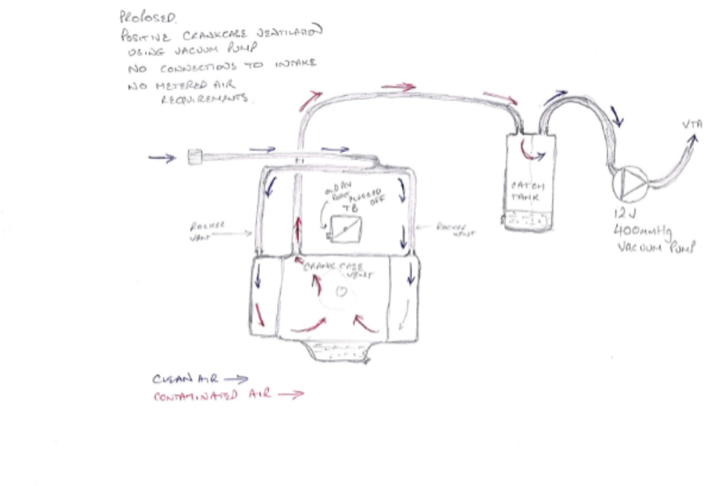
Ta, Andy
Really interesting discussion, and useful information. I'm glad I started the thread, I should visit more often!
My quest was nothing to do with keeping the intake clean, I just wanted an intake pipe with no connections!
I am now really keen to retain a 'forced' crankcase ventilation system.
I can't use the engine's suction for this without returning to the intake pipe, or causing potential metered air issues.
I need an independent suction source. I'm really interested in 2pots exhaust venturi once it's been tried and tested. Meantime the race season is approaching and I must get my butt into gear and get my intake sorted.
I'm going to install something like this rubbish diagram, I need to source a 12v 400mmHg vac pump and a catchtank.
Please feel free to take the ****, laugh out loud, or maybe just constructively critcise

Ta, Andy
My quest was nothing to do with keeping the intake clean, I just wanted an intake pipe with no connections!
I am now really keen to retain a 'forced' crankcase ventilation system.
I can't use the engine's suction for this without returning to the intake pipe, or causing potential metered air issues.
I need an independent suction source. I'm really interested in 2pots exhaust venturi once it's been tried and tested. Meantime the race season is approaching and I must get my butt into gear and get my intake sorted.
I'm going to install something like this rubbish diagram, I need to source a 12v 400mmHg vac pump and a catchtank.
Please feel free to take the ****, laugh out loud, or maybe just constructively critcise
Ta, Andy
Vac pump info:
http://forums.nasioc.com/forums/showthread.php?t=667007
Interesting to see Paul from Zen posting in the thread - May be worth contacting him.
http://forums.nasioc.com/forums/showthread.php?t=667007
Interesting to see Paul from Zen posting in the thread - May be worth contacting him.

The smaller head take offs I have blanked so just running 1 from either side into catch can
Crank also into can - to vent
Also worth noting
In the colder winter months your crank vent will extract more moisture than the heads , so you may find your can full of water ( don't be alarmed
This is actually a good thing
I certainly wouldn't want all that circulating & returning
Summer months no probs with moisture
Shows that it is indeed cleaning & extracting
That's my 2p worth


My 2 year old can draw better than that, but it's better than I can do LoL. Seriously, however you set it up regarding PCV & vents etc, do not make the mistake of under estimating the port size you need to run decent power & boost. I had a serious problem with the ports being too small on my last can causing blue smoking & oil burning while being driven hard & it was a Subaru specific one. Paul Finch kindly helped me diagnose this in the end but it gave me a real headache & cost a lot to resolve such a simple design fault. The big port OBP can which I now run has 14mm inlet ports 3 of them & a 22mm port for the vent. Some people think the port size is excessive but after the grief Iv had with it I'd never go any smaller again as the set up advised by Paul now works perfectly.
As for the diagram above, it's fine I get it! Looks like it would work fine to me as long as the pump was up to it. Most of the electric pumps I have seen have been quite low powered. Again you don't want massive power or you may actually suck your oil out lol.
If I can work it out I will actually fit a boost/vac gauge to the PCV and turbo vent lines as well as the rocker breathers. I will then give you all the figures for pressure or vacuum on and off boost/at tick over etc. Then we will know what sort of things exist in the stock system.
Last edited by FMJ; Feb 27, 2014 at 12:10 PM.
Ok, spare boost/vacuum gauge brought. I will measure the pressure or vacuum on the OE system on a classic MY00 mapped to 18psi on a TD04 at:
Rocker breather pipes
Pipe between PCV and crank breather
Pipe between turbo inlet and crank vent (post the divide)
I will take measurements at idle, at part throttle cruising, on overrun, on full boost.
By knowing what the stock system does (not just the theory) we will know what we should maybe replicate or improve on. It also means when I fit a new setup I will know if it is better, the same or worse.
However my car is off the road for a few weeks yet so you will have to be patient.
See I wondered about this. But on the stock setup when the PCV closes on boost the actual hole in the t piece from the crank is TINY! it's an oval about 8mm by 4mm. All that crank pressure through that tiny hole. I guess this is why despite the rocker covers supposed to take clean air in they do infact blow crap out too when pressure gets high as its the easiest way out on boost.
As for the diagram above, it's fine I get it! Looks like it would work fine to me as long as the pump was up to it. Most of the electric pumps I have seen have been quite low powered.
As for the diagram above, it's fine I get it! Looks like it would work fine to me as long as the pump was up to it. Most of the electric pumps I have seen have been quite low powered.
http://bbs.22b.com/forums/showthread...-sump-any-good
GM 24505066 air pump http://www.ebay.co.uk/itm/GM-OEM-245...item257cd5251f
Last edited by 2pot; Feb 27, 2014 at 03:52 PM. Reason: add link
Interesting items from the nasioc vac pump thread:
Mercedes Benz 111 018 03 35 air oil separator
http://www.ebay.co.uk/itm/Mercedes-R...item51b5379c56
FT020 flow tube
http://www.anver.com/document/vacuum...bes/ft020!.htm
Mercedes Benz 111 018 03 35 air oil separator
http://www.ebay.co.uk/itm/Mercedes-R...item51b5379c56
FT020 flow tube
http://www.anver.com/document/vacuum...bes/ft020!.htm
Last edited by 2pot; Feb 27, 2014 at 06:15 PM.

Thread
Thread Starter
Forum
Replies
Last Post
Wingnuttzz
Member's Gallery
30
Apr 26, 2022 11:15 PM
Adam Kindness
ScoobyNet General
0
Sep 15, 2015 03:31 PM