Computational Fluid Dynamic Analysis of an Impreza CAD model
 26 December 2012, 10:39 PM
#1
Scooby Regular
Thread Starter

Join Date: Jan 2006
Location: North Wales
Posts: 931
Likes: 0
Received 0 Likes
on
0 Posts
Thought I’d share a different sort of project with you. After conducting various projects in University with the use of Star CCM+ CFD software I managed to get some time to run some analysis on an Impreza 22B model using the Uni licenses.
Now I’m sure this project will take the interest of people who have no idea about CFD analysis as well as some of you who may be more familiar with CAD and computer analysis software, so I will try my best to keep it simple but also include details on what it’s all about.
The initial CAD model of the 22B isn’t great and took a lot of work to get the surface to be a suitable quality that would mesh. Meshing is a process of breaking the CAD model up into finite cells through which the airflow theoretically flows, so in each cell numerous equations are undertaken that evaluate the velocities, pressures, direction etc. of the air flow. The finer the mesh the more accurate the results but the longer the simulation will take. As I don’t have a supercomputer I have to compromise on the mesh quality but ensuring it is refined in the key areas will still yield accurate results.
Some of you may feel that the CAD model is lacking detail such as vents that actually go somewhere or the voids around the engine etc. However, it is common place to simplify models to use in CFD and actually this is a more detailed model than most would use. The wheels have been simplified also which is because my mesh would include too many cells if I add too much details but I may change this in future simulations.
This first analysis did not include the spoiler as I didn’t feel the geometry was correct. It was run at 29ms-1 which is roughly 65mph. The simulation includes rotating wheels and a moving ground plane to be as realistic as possible.
The results showed a total drag force on the car of 335N which is about 34kg trying to hold the car back. This results in a drag co-efficient of 0.33 and after doing some research I could only find a drag co-efficient of a newage being tested in a wind tunnel which was 0.34 so I can assume the simulation to be relatively accurate. The lift created at this speed showed to be -14.6N which is about -1.5kg of downforce. Most road cars will not make downforce, they usually make positive lift due to the obstructions under the car so a low downforce value seems reasonable seeing as the vehicle underbody is simplified somewhat.
Here are some graphics to show you what this all actually means.
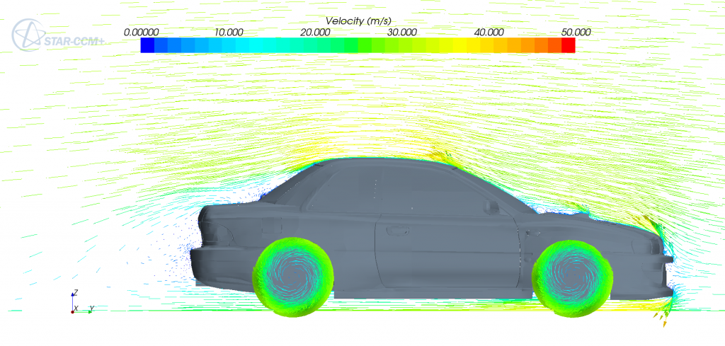
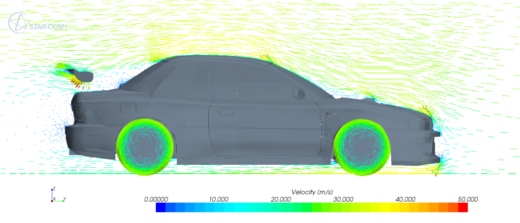
This is vector scene which depicts the direction of the airflow as arrows which are coloured according to their airspeed. It shows how the air crashes into the front and is deflected over the bonnet and under the bumper as you would expect. You can see that air clings to the bonnet and successfully enters the scoop. There is a pocket of stationery air at the bottom of the windshield. The air flowing over the roof accelerates causing low pressure. the air separates from the rear window somewhat which will increase drag and reduce airflow to the rear wing. And finally you can see a pocket of stagnant air at the rear of the vehicle which you have to drag around.
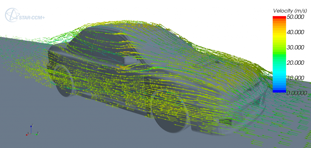
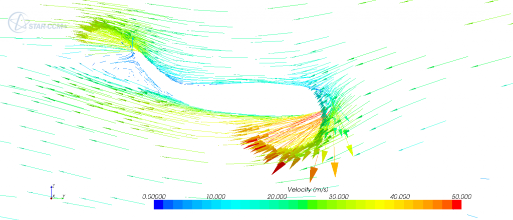
This is also a vector scene but depicts streamlines that initiate from a location upstream, like a smoke wand would in a wind tunnel. This shows how the air flows around the car. I can get more views of this if anyone is interested.
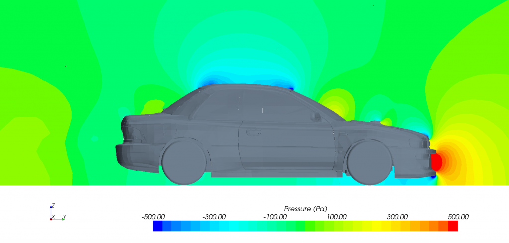
This is a scalar scene which shows the pressures around the car on a plane which cuts the car down the middle. Pressures are in Pa where 100,000 Pa = 1Bar. This scalar scene shows how the pressures are effected even upstream of the car to quite a distance.
Now I have done this basic analysis I will probably go about testing other parameters such as finding the centre of pressure, add a spoiler, splitter, canards, diffuser and so on. Hopefully this will show you what possible gains are available aerodynamically. Although this will take a lot of time so updates are likely to be slow!
Feel free to suggest any other things you’d like to see tested or if you just want to know more about that initial simulation. I can also do design and analysis work if anyone wants to hire me… I can do this stuff all day and am looking for a career in this sort of area.
Thanks for looking.
Gaz
Now I’m sure this project will take the interest of people who have no idea about CFD analysis as well as some of you who may be more familiar with CAD and computer analysis software, so I will try my best to keep it simple but also include details on what it’s all about.
The initial CAD model of the 22B isn’t great and took a lot of work to get the surface to be a suitable quality that would mesh. Meshing is a process of breaking the CAD model up into finite cells through which the airflow theoretically flows, so in each cell numerous equations are undertaken that evaluate the velocities, pressures, direction etc. of the air flow. The finer the mesh the more accurate the results but the longer the simulation will take. As I don’t have a supercomputer I have to compromise on the mesh quality but ensuring it is refined in the key areas will still yield accurate results.
Some of you may feel that the CAD model is lacking detail such as vents that actually go somewhere or the voids around the engine etc. However, it is common place to simplify models to use in CFD and actually this is a more detailed model than most would use. The wheels have been simplified also which is because my mesh would include too many cells if I add too much details but I may change this in future simulations.
This first analysis did not include the spoiler as I didn’t feel the geometry was correct. It was run at 29ms-1 which is roughly 65mph. The simulation includes rotating wheels and a moving ground plane to be as realistic as possible.
The results showed a total drag force on the car of 335N which is about 34kg trying to hold the car back. This results in a drag co-efficient of 0.33 and after doing some research I could only find a drag co-efficient of a newage being tested in a wind tunnel which was 0.34 so I can assume the simulation to be relatively accurate. The lift created at this speed showed to be -14.6N which is about -1.5kg of downforce. Most road cars will not make downforce, they usually make positive lift due to the obstructions under the car so a low downforce value seems reasonable seeing as the vehicle underbody is simplified somewhat.
Here are some graphics to show you what this all actually means.
This is vector scene which depicts the direction of the airflow as arrows which are coloured according to their airspeed. It shows how the air crashes into the front and is deflected over the bonnet and under the bumper as you would expect. You can see that air clings to the bonnet and successfully enters the scoop. There is a pocket of stationery air at the bottom of the windshield. The air flowing over the roof accelerates causing low pressure. the air separates from the rear window somewhat which will increase drag and reduce airflow to the rear wing. And finally you can see a pocket of stagnant air at the rear of the vehicle which you have to drag around.
This is also a vector scene but depicts streamlines that initiate from a location upstream, like a smoke wand would in a wind tunnel. This shows how the air flows around the car. I can get more views of this if anyone is interested.
This is a scalar scene which shows the pressures around the car on a plane which cuts the car down the middle. Pressures are in Pa where 100,000 Pa = 1Bar. This scalar scene shows how the pressures are effected even upstream of the car to quite a distance.
Now I have done this basic analysis I will probably go about testing other parameters such as finding the centre of pressure, add a spoiler, splitter, canards, diffuser and so on. Hopefully this will show you what possible gains are available aerodynamically. Although this will take a lot of time so updates are likely to be slow!
Feel free to suggest any other things you’d like to see tested or if you just want to know more about that initial simulation. I can also do design and analysis work if anyone wants to hire me… I can do this stuff all day and am looking for a career in this sort of area.
Thanks for looking.
Gaz
 27 December 2012, 11:14 AM
#4
Scooby Regular
iTrader: (3)

Join Date: Aug 2003
Location: AL4 | W1B
Posts: 2,699
Likes: 0
Received 0 Likes
on
0 Posts
That is quite interesting, it would be interesting to see what happens if/when you added the vents in? And also if the undertray actually makes a difference or not.
27 December 2012, 11:43 AM
#5
Scooby Regular
iTrader: (2)

Join Date: Oct 2002
Location: Aldershot
Posts: 1,861
Likes: 0
Received 0 Likes
on
0 Posts
Just noticed the logo in the corner, cad model of the impreza looks good from what I can make out, would like to have a go but think my surfacing isn't up to it yet
27 December 2012, 01:19 PM
#6
Scooby Regular
Thread Starter
Join Date: Jan 2006
Location: North Wales
Posts: 931
Likes: 0
Received 0 Likes
on
0 Posts
This type of CAD model and simulation is mainly for aerodynamic analysis of the outer body not internal flows etc. It is more than suitable for this sort of work, for example using the vector scene I showed, you can identify where the airspeed is highest at the rear of the vehicle which gives you the best location to mount your spoiler etc. I think the next stage for this model is to design the current spoiler that is on my car and see what gains it actually gives, if any.
Gaz
27 December 2012, 06:35 PM
#7
Scooby Regular
iTrader: (2)
Join Date: Oct 2002
Location: Aldershot
Posts: 1,861
Likes: 0
Received 0 Likes
on
0 Posts
Opening the vents would then require an engine and radiators to be modeled really, which would just add to much detail for the computer I am using to mesh it effectively but I can do it, would just take forever to mesh and run. If they were opened up the major change would be that some of the high pressure air entering the front bumper and the bonnet vent would find its way to the underside which would increase the under body pressure. However, this would be minimal because the obstructions caused by the engine and gearbox would not allow much flow. This would probably eliminate the small amount of down force the model is showing though. As for the undertray, I would imagine this would increase airspeed at the front of the car under side slightly which would lead to lower pressures under the car.
The CFD software is Star CCM+. The CAD model was actually downloaded by a friend who siad it was a Forza model but he managed to convert it into a file type suitable for use in most CAD suites. I mainly use Solidworks and Catia V5. The surfacing of the downloaded model was not great and had several holes but using some of the tricks in the CFD software I was able to get the surface wrapper to close the holes ready for its final mesh. You could close the holes in a CAD suite but many of them were too small to see so the automatic gap closure in CFD was my best option.
This type of CAD model and simulation is mainly for aerodynamic analysis of the outer body not internal flows etc. It is more than suitable for this sort of work, for example using the vector scene I showed, you can identify where the airspeed is highest at the rear of the vehicle which gives you the best location to mount your spoiler etc. I think the next stage for this model is to design the current spoiler that is on my car and see what gains it actually gives, if any.
Gaz
Trending Topics
27 December 2012, 06:46 PM
#8
Scooby Regular
Thread Starter
Join Date: Jan 2006
Location: North Wales
Posts: 931
Likes: 0
Received 0 Likes
on
0 Posts
I couldn't figure out how to convert a forza model myself but they are about on the internet, like I said I didn't find the model just fixed it after.
Gaz
Gaz
27 December 2012, 07:15 PM
#9
I've often wondered how this would affect handling on a road going car...
http://www.iwsti.com/forums/gd-membe...7-video-3.html
http://www.iwsti.com/forums/gd-membe...7-video-3.html
27 December 2012, 11:01 PM
#10
Scooby Regular
Thread Starter
Join Date: Jan 2006
Location: North Wales
Posts: 931
Likes: 0
Received 0 Likes
on
0 Posts
From my experience, flattening off the underside of the car like that gives very good gains in downforce due to accelerated air flow leading to lower pressures and as the pressure acts on such a large area results in good forces. Probably more than you might think especially as downforce squares with speed. So say something like that might give you 50N [~5kg] downforce at 30mph, at 60mph will result in 200N [~20kg]. I will model something like that for you not too long from now and see what we do get.
I should say that although CFD gives fairly good approximations on whats going on it does have a tenancy to under predict drag and over predict lift/downforce due to the difficulties in modeling separation of airflow and turbulence. But still the figures will be in the right ball park.
Gaz
I should say that although CFD gives fairly good approximations on whats going on it does have a tenancy to under predict drag and over predict lift/downforce due to the difficulties in modeling separation of airflow and turbulence. But still the figures will be in the right ball park.
Gaz
27 December 2012, 11:05 PM
#11
Scooby Regular
Thread Starter
Join Date: Jan 2006
Location: North Wales
Posts: 931
Likes: 0
Received 0 Likes
on
0 Posts
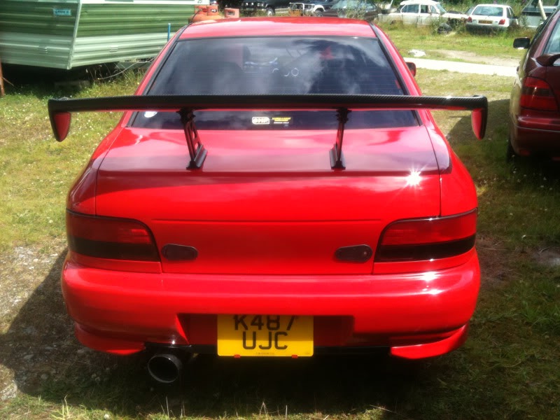
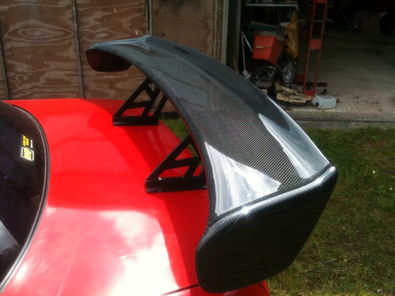
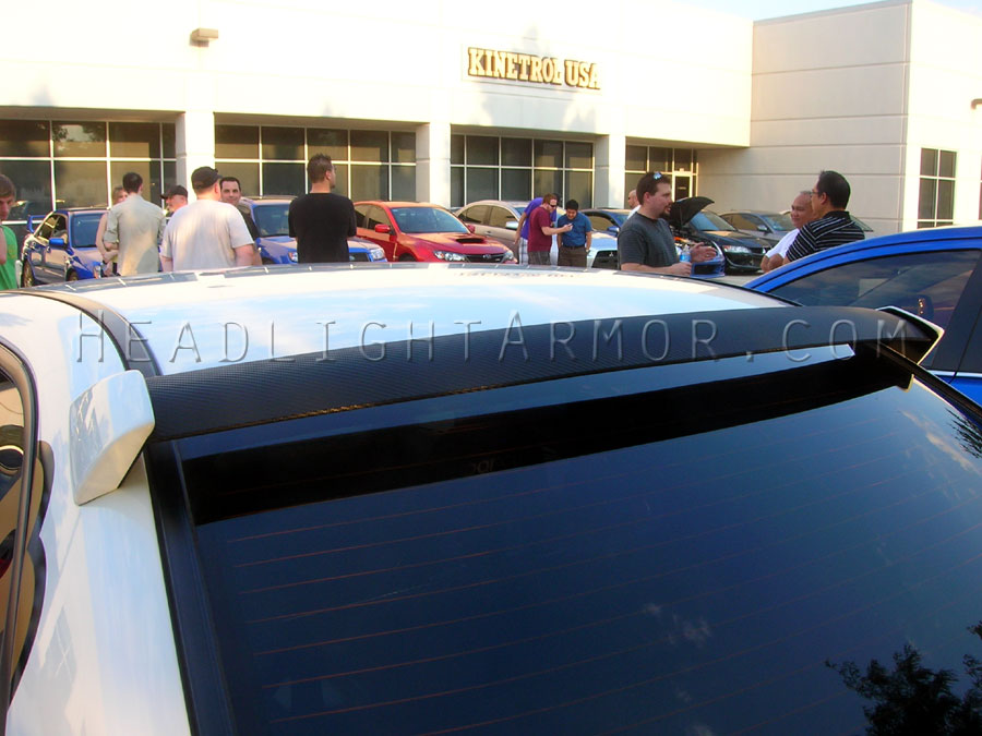
So I’ve managed to model my spoiler fairly accurately in CAD ready to test in the CFD simulation. The spoiler is shown below on the actual car and in the CFD model.
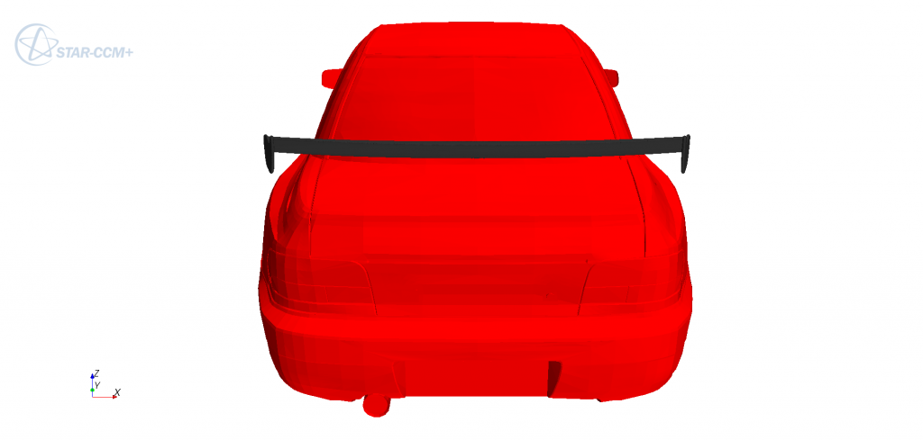
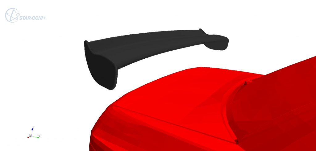
This spoiler is a cheap carbon fibre one and I didn’t really think it had the best of profiles to it. Although the underside has a good curve to it, the upper surface is cambered to quite a high degree where the maximum camber occurs quite far back on the wings chord. This probably will cause a lot of drag but also may induce the high pressures I’m looking for, for good downforce.
This wing can be angled in two positions, but as the air flow is already aiming at a downward angle due to the rear window geometry (as shown by the earlier vector scene) I chose to keep the wing at its more level setting so not to cause separation of the airflow. Hopefully the CFD will show me if my thoughts were along the right lines.
The simulation will be done shortly so will post results later.
Gaz
29 December 2012, 04:50 PM
#12
Scooby Regular
Thread Starter
Join Date: Jan 2006
Location: North Wales
Posts: 931
Likes: 0
Received 0 Likes
on
0 Posts
The results of the spoiler simulation are in:
Without Spoiler : Drag = 335N, Lift = -14.5N
With Spoiler : Drag =389N, Lift = -295N
So at 65mph that spoiler is pushing down on the car with about 30kgs but as I said this CFD tends to over predict lift and under predict drag but even 20kgs is going to help somewhat.
Analysing the visual scenes shows how the wing diverts airflow up which creates a bigger stagnation region at the rear of the car which is where a lot of the drag increase comes from.
Also, you can see the airflow separates quite early on at the rear of the wing which will give less performance that the wing is capable of. The reason for this is probably the angle which the air flows down the rear window, which I suggested might be the case before, leading to the wing having a higher angle of attack. I think I will rotate the wing slightly and re run the sim to see if I get better performance.
If I'm right about it, you may want to re-adjust you wings angle of attack, if you can that is.
Gaz
Last edited by GazJenno; 29 December 2012 at 04:53 PM.
29 December 2012, 10:25 PM
#13
Apart from the rear spoiler are the orange/darker yellow area's of "bad aerodynamics"?.
Do you have any figures of any comparable cars like an Evo, 911, M3 etc to compare how aerodynamic they are or how much drag they have?.
Very interesting project bud, keep up the good work.
Do you have any figures of any comparable cars like an Evo, 911, M3 etc to compare how aerodynamic they are or how much drag they have?.
Very interesting project bud, keep up the good work.
30 December 2012, 03:13 PM
#14
Scooby Regular
Thread Starter
Join Date: Jan 2006
Location: North Wales
Posts: 931
Likes: 0
Received 0 Likes
on
0 Posts
Apart from the rear spoiler are the orange/darker yellow area's of "bad aerodynamics"?.
Do you have any figures of any comparable cars like an Evo, 911, M3 etc to compare how aerodynamic they are or how much drag they have?.
Very interesting project bud, keep up the good work.
Do you have any figures of any comparable cars like an Evo, 911, M3 etc to compare how aerodynamic they are or how much drag they have?.
Very interesting project bud, keep up the good work.
The only other full car I have at the moment to compare the Impreza to is a Honda Integra DC5. Which at the same speed showed a drag value of 332N compared to the Impreza 335N and lift values of -41N compared to the -14.5N of the Impreza. The Integra did have a smoother under body in the model, although I think the rear bumper has been modeled poorly, and has a slightly smaller frontal area. But again, the Integra values compared very closely with data available from Honda wind tunnel testing the actual car.
Gaz
30 December 2012, 04:12 PM
#15
Do you mean in the vector scene (one with the little arrows) or in the scalar scene. In the vector scene the orange/ darker parts represent areas of high speed which you kind of want if its in the right places. In the scalar scenes the orange and red bits are showing high pressures. Its the location of the airflow speed and pressures that determine how good aerodynamically the car is so its kind of relative to what area your looking at.
The only other full car I have at the moment to compare the Impreza to is a Honda Integra DC5. Which at the same speed showed a drag value of 332N compared to the Impreza 335N and lift values of -41N compared to the -14.5N of the Impreza. The Integra did have a smoother under body in the model, although I think the rear bumper has been modeled poorly, and has a slightly smaller frontal area. But again, the Integra values compared very closely with data available from Honda wind tunnel testing the actual car.
Gaz
I wish I knew the very basics of aerodynamics, Its rarely talked about on this site, power, more power and a little less weight.
Last edited by Kwik; 30 December 2012 at 04:24 PM.
30 December 2012, 05:12 PM
#16
I'd like to see any screen caps of the DC5 as i used to have one of them!
They do look alot sleeker than the scooby and it'd be interesting to see if the wing on it did anything, as some people claimed it did help quite a bit with high speed stability and others said it was just chav nonsence!
They do look alot sleeker than the scooby and it'd be interesting to see if the wing on it did anything, as some people claimed it did help quite a bit with high speed stability and others said it was just chav nonsence!
 02 January 2013, 09:22 PM
#18
How would the Hawkeye rear window spoiler affect airflow onto rear wing.? Is it meant to pass air over itself, thus forcing the air higher over the back and onto the rear wing or is the air meant to flow u under the rear window spoiler? Great work BTW
02 January 2013, 09:44 PM
#20
09 January 2013, 02:47 PM
#21
Scooby Regular

Join Date: Mar 2011
Location: Germany
Posts: 71
Likes: 0
Received 0 Likes
on
0 Posts
By the way, this effect increases with larger splitters (until a threshold of course) and is the reason, why Pikes Peak cars go pretty bonkers with them. There is also a short description on Wikipedia, if I failed again at explaining it in textual form
http://en.wikipedia.org/wiki/Splitte...ive)#SplittersI'm not entirely convinced, that a huge splitter makes any sense on a road car also due to the low everyday speeds. But on a track, it can make a lot of a difference in front end grip, as demonstrated by Top Gear on their 24h race. Their splitter fell off and after that, they started shredding the tires.
So this is my go at interpreting all the flow data. I'm not an expert but have written some visualization software for stuff like this. So anyone feel free to correct any mistakes in my interpretation
And a big thanks to Gaz for doing these simulations. I've been looking for data like this for quite some time but couldn't find any available for public.
Cheers,
Jürgen
09 January 2013, 03:02 PM
#22
Scooby Regular

tis an interesting one that. does show alot of balooning from the bonnet and the scoop area sufferes from it as well.
have you go models of any of the new ages to see how they react?
have you go models of any of the new ages to see how they react?
09 January 2013, 04:53 PM
#23
Scooby Regular
Thread Starter
Join Date: Jan 2006
Location: North Wales
Posts: 931
Likes: 0
Received 0 Likes
on
0 Posts
Sorry guys, I have been crazy busy the last few weeks but promise I will do more on this soon and get the screen shots and other data some of you have asked for. I'll see if I can find a newage model too. Thanks for the interest.
Gaz
Gaz
10 January 2013, 05:29 PM
#24
So are we saying that this type of spoiler below helps push air underneath it or helps push air over the top & thus further along the rear?
The reason I ask is because I have a spoiler as in the pic below and wondering if in fact this is causing more drag by pushing the air higher up rather than lower down over the rear screen? Or am I over simplifying it all!

The reason I ask is because I have a spoiler as in the pic below and wondering if in fact this is causing more drag by pushing the air higher up rather than lower down over the rear screen? Or am I over simplifying it all!
Last edited by rickya; 10 January 2013 at 05:34 PM.
10 January 2013, 05:36 PM
#25
Scooby Regular
Thread Starter
Join Date: Jan 2006
Location: North Wales
Posts: 931
Likes: 0
Received 0 Likes
on
0 Posts
That type of spoiler is aimed to keep airflow attached down the rear window and along the boot. It should improve flow to the rear wing and also help to reduce drag to a point... Again though, if I get time I will try and model one and see what it does so I can show it graphically.
Gaz
Gaz
10 January 2013, 06:10 PM
#27
Scooby Regular
Join Date: Mar 2011
Location: Germany
Posts: 71
Likes: 0
Received 0 Likes
on
0 Posts
So are we saying that this type of spoiler below helps push air underneath it or helps push air over the top & thus further along the rear?
The reason I ask is because I have a spoiler as in the pic below and wondering if in fact this is causing more drag by pushing the air higher up rather than lower down over the rear screen? Or am I over simplifying it all!
The reason I ask is because I have a spoiler as in the pic below and wondering if in fact this is causing more drag by pushing the air higher up rather than lower down over the rear screen? Or am I over simplifying it all!
The smaller spoiler on your second pic should direct the air higher above your boot spoiler which might not be ideal as depicted from Gaz' simulation run with the boot spoiler. At least with a non-adjustable boot spoiler at a similar angle that is. This small spoiler might also produce another vortex between the spoiler lip and the window -> small bit of extra drag as with the angled one. It might also increase the drag area at the lower end of the rear window due to the reduced airflow.
This will get a lot clearer, once you see the simulation images
10 January 2013, 07:18 PM
#28
Scooby Regular
Thread Starter
Join Date: Jan 2006
Location: North Wales
Posts: 931
Likes: 0
Received 0 Likes
on
0 Posts
I agree with what JuergenG had to say about the second spoiler... I never saw the second pic initally. It's going to be a while before I do some more sims on this but I will get round to it.

 16 January 2013, 11:18 PM
#30
Scooby Newbie

Join Date: Jan 2013
Location: Sydney, Australia
Posts: 3
Likes: 0
Received 0 Likes
on
0 Posts
Great work, this is something I've been wanting to do for a while but I've never had the time to get an accurate CAD model / 3D scan of the car :P
I've just got a few queries / observations:
- That airfoil section you're using for the wing has pretty extreme camber in the latter half, I think you're going to struggle to find an angle where it will exhibit no flow separation.
- I'd like to know more about your mesh, roughly how many elements / were you able to get an inflation layer to work / any pictures?
- What turbulence model(s) have you tried for this simulation? I would think that SST or similar would be a good choice for this particular problem. K-e will likely wildly under-predict drag.