When you click on links to various merchants on this site and make a purchase, this can result in this site earning a commission. Affiliate programs and affiliations include, but are not limited to, the eBay Partner Network.
My 2006 Impreza started overheating and when I stopped I noticed 2 things; the header tank had ejected a lot of it's contents and the radiator fans didn't come on. They both turn on if the A/C is turned on. The dash fault indicator doesn't come on.
I checked all fuses and the fan relays which are fine. There is a voltage on one pin of the coil of the main fan relay, but the other side of the relay coil never gets grounded, even when the temp is 99C and the car is stationery. If I ground that side of the coil the relay turns on and the fan runs. After a while the dash fault indicator comes on.
From the wiring diagram I see that the relay is turned on by the ECM grounding that side of the relay which it's not doing. Does this mean that the ECM is faulty or could it be something else (hopefully!)?
***Updated due to not being RHD turbo model but a LHD 1.6L SOHC model
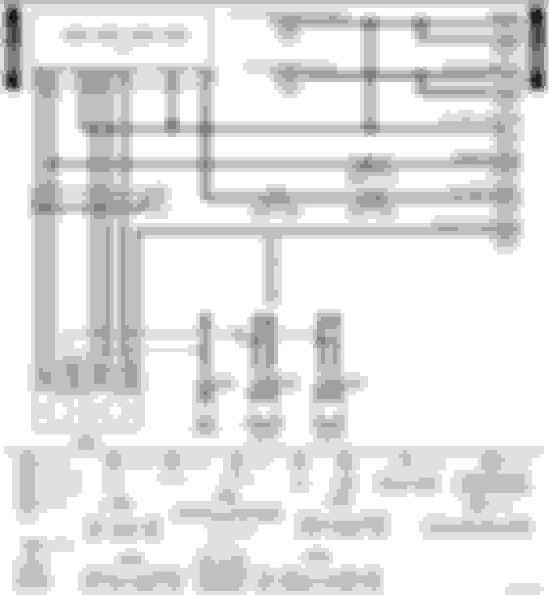
Wiring for European MY06/07 Impreza non turbo models attached.
Yes the ECU grounds the relay coils to operate the fans but if both work when the A/C is turned on the ECU is doing its thing.
I would check/replace that both the "Coolant temp sensor/thermometer" circuits are working.
Pins 1&2 - ECU temp circuit
PIn 3 - Dash gauge
One side of the dash gauge is earthed via the sensor body hence the copper washer - no thread tape
Last edited by Don Clark; Jan 15, 2024 at 04:14 PM.
The temp coolant sensor was replaced very recently when it failed. When I monitor the temp using my ODBC reader as the car warms up and the thermostat opens, the temps seem to be totally normal. Also, I've checked the top/bottom hose temps using an IT thermometer and it confirms what my reader is showing.
I'll check the wiring from the fuse box back to the ECU - maybe there's an issue.
Hi Don,
Thanks for that. Sorry that I didn't spell it out at the top of my post. Mine is a LHD, 2006, non-turbo Impreza with SOHC. Engine EJ16.
Maybe it's easiest if I just check continuity from the fusebox to the ECU, and also the voltage at the relevant pin on the ECU?
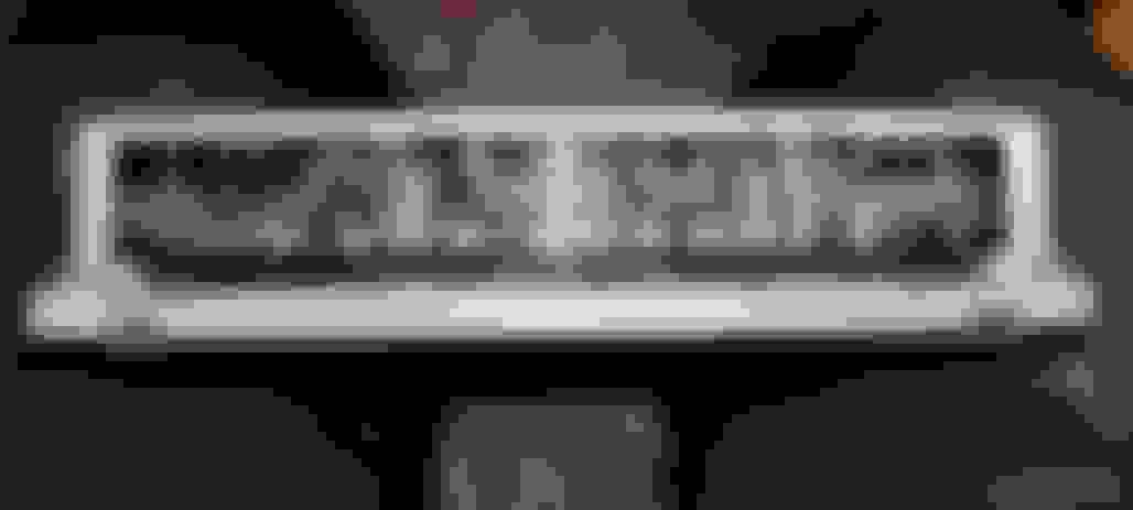
I've pulled the ECU and it doesn't match any of the diagrams I see in my workshop manual. There are 4 connectors, each with 3 rows of pins. How do I know which is the main fan control pin?
Thanks!
OK.
Have attached both correct Fan diagram and ECU pinout for the H4SO engines as pdf's
And have updated previous replies due to in correct model info.
ECU as far as I can tell should be a 22611AL230 ??
In the European manuals only the main engine outputs are listed for the ECUpinouts
The fan control pin numbers will need to be confirmed from the fan wiring diagram for wire colour and pin location.
Last edited by Don Clark; Jan 15, 2024 at 04:50 PM.
Just to confirm that I'm testing the correct pins:
Fan 1 is pin #14 on B134 the connector furthest left, and counting pins in the middle row starting at #9 from the right (ECM pinout diagram) looking into the back of the ECM. From the Non Turbo Fans diagram it starts #9 from the left!
Fan 2 is pin #13.
Are these 2 wires coloured RL and GW (whatever those colours are)? Not sure it helps me much as I'm partially colour blind so I might have to ask for help.
One diagram shows the face of the ECU the other the face of the connecting plug
distinguished by the solid black and clear rectangles. You will have to confirm which is which in this inst with the wire colours.
ECM diagram
Fan diagram
Colours: RL is Red/bLue stripe; GR is Green/White stripe
Last edited by Don Clark; Jan 16, 2024 at 11:52 AM.
When the ECU/ECM receives the required voltage signal from the Engine coolant temp sensor the ECU will ground pin A14 and turn on the fan
Engine coolant temp sensor sends signal to B135 pin12 - as per ECM pinout.
When the A/C control unit sends the "on" signal to the ECU (either B137 pin D13 or B136 pin C11) the ECU grounds both fans via pins A14 and A13
AS you said in your original post "They both turn on if the A/C is turned on." i believe the problem lies in the coolant temp side of things.
For the non turbo models the Coolant temp gauge is a separate circuit from the ECU signal although part of the same sensor.
Either the ECU is not receiving the signal from the sensor (B135 pin12) or the ECU's circuitry for this input is not grounding A14.
Make sure B135 pin19 is grounded
In fact probably make sure all the engine grounds are good and clean.
Please help, I need a diagram for this ECU to fix the connections because I have thes
Originally Posted by Don Clark
OK.
Have attached both correct Fan diagram and ECU pinout for the H4SO engines as pdf's
And have updated previous replies due to in correct model info.
ECU as far as I can tell should be a 22611AL230 ??
In the European manuals only the main engine outputs are listed for the ECUpinouts
The fan control pin numbers will need to be confirmed from the fan wiring diagram for wire colour and pin location.
Please help. The engine was replaced from 1.6 to 2.0 and the ECM was replaced from 3 pin to 4 pin and these problems appeared. I have a manual gearbox, not an automatic, and I have a CO sensor, not an oxygen sensor.
sensor
my car 2004 SOHC
Please help. The engine was replaced from 1.6 to 2.0 and the ECM was replaced from 3 pin to 4 pin and these problems appeared. I have a manual gearbox, not an automatic, and I have a CO sensor, not an oxygen sensor.
sensor
my car 2004 SOHC
Also relevant for 2.0L SOHC (H4SO) of 2004/05 which if a European model also uses a 4 plug ECU.
You have two Oxygen sensors the front one is an Air/Fuel (AF) sensor which usual burns out its heater (P0031)
If it had a 3 plug ECU it would have been an H4SO without Onboard Diagnostics (ODBII) support
Pinout attached, it still has an oxygen sensor also known as a Lambda sensor
If it had a 3 plug ECU it would have been an H4SO without Onboard Diagnostics (ODBII) support
Pinout attached, it still has an oxygen sensor also known as a Lambda sensor
This is an old ECM, please send me a schematic for it. Thank you.


 or could it be something else (hopefully!)?