When you click on links to various merchants on this site and make a purchase, this can result in this site earning a commission. Affiliate programs and affiliations include, but are not limited to, the eBay Partner Network.
We all know Subaru's positive crankcase breather system is not up to taking hard driving, extra boost or blow by.
Excessive amounts of oil gets into your intake track coating the inside of your intercooler and reducing its efficiency, Then over night this oil drains down out of your intercooler and pools by your throttle body,
When you start your engine in the morning you get a puff of embarrassing blue smoke.
Not only that it reduces the octane of your air fuel mixture.
Causes carbon deposits to form in your engine.
And excessive oil consumption.
Fitting a catch can or a Air oil separator is the best solution.
There are many benefits to a positive crankcase ventilation system.
It supply's a constant flow of fresh air to remove harmful gasses from the crank case.
Helps to keep your oil in better condition reducing corrosion from acid build up in the oil.
It's also better for the environment as less harmful gases are past into the atmosphere as there re burnt in the combustion chamber.
It can also apparently help to reduce fuel consumption.
If you care about that last one you most likely have the wrong car.
Anyway after browsing the web and looking at the extortionate prices company's are charging for what is technically a red bull can with some pipes in it I've decided to make up my own system.
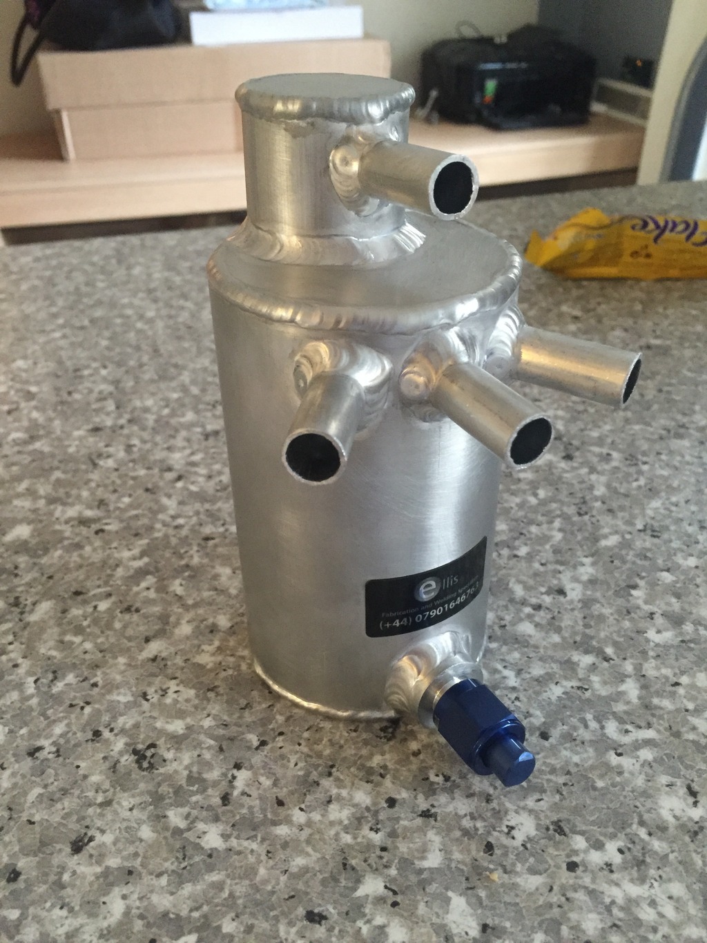
I got in touch with Ellis fabrication and welding and had them build me a custom catch can.
I supplied them with sketch of the cans dimensions, mounting bracket location and size of the ports.
Rich did a top job building it to my spec and had it sent out to me within days.
The can he built is a baffled 3 port catch can with one inlet for the crank case, Two inlets for both head breathers with a single return vent on top.
It also has a An6 fitting at the bottom for the ability of fitting a return to sump drain pipe and a An6 blanking cap if you wish not to use it.
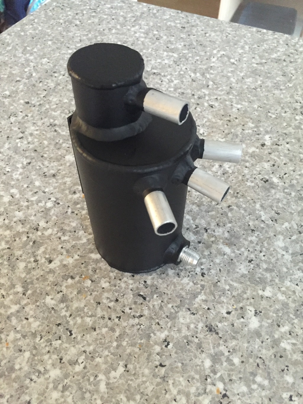
The can comes in aluminium but I painted it using a acid etch primer and a black high temp spray paint as I wanted to keep the engine bay looking as oem as possible, I also used black hose's and fittings for a more stealthy install.
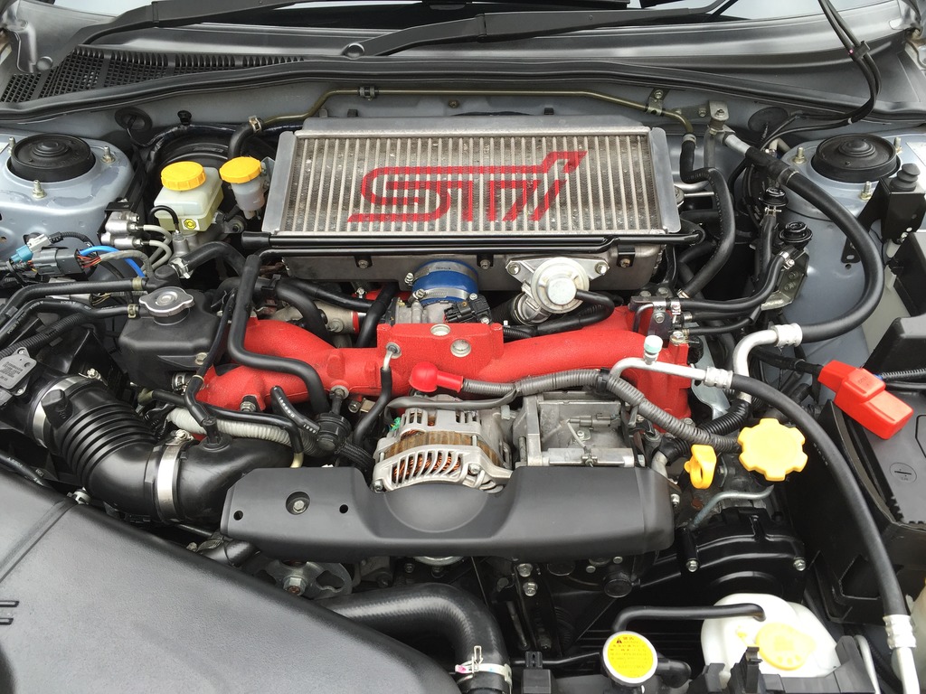
I also had the idea of using the original metal breather pipe that's mounted on the front of the intercooler as part of the vent to intake pipe work.
This is much neater than having a rubber hose draped across the engine like most installs I've seen.
Due to the lack of space in my engine bay I had the dimensions of the can and bracket made to fit in the area where the secondary air pump used to be located, There was already two m6 threaded holes in the body work at exactly 50mm apart from each other.
Finally I also decided to use the return to sump drain pipe as then there be no need for regular emptying of the can.
But cleaning out the can every oil change would be a good idea.
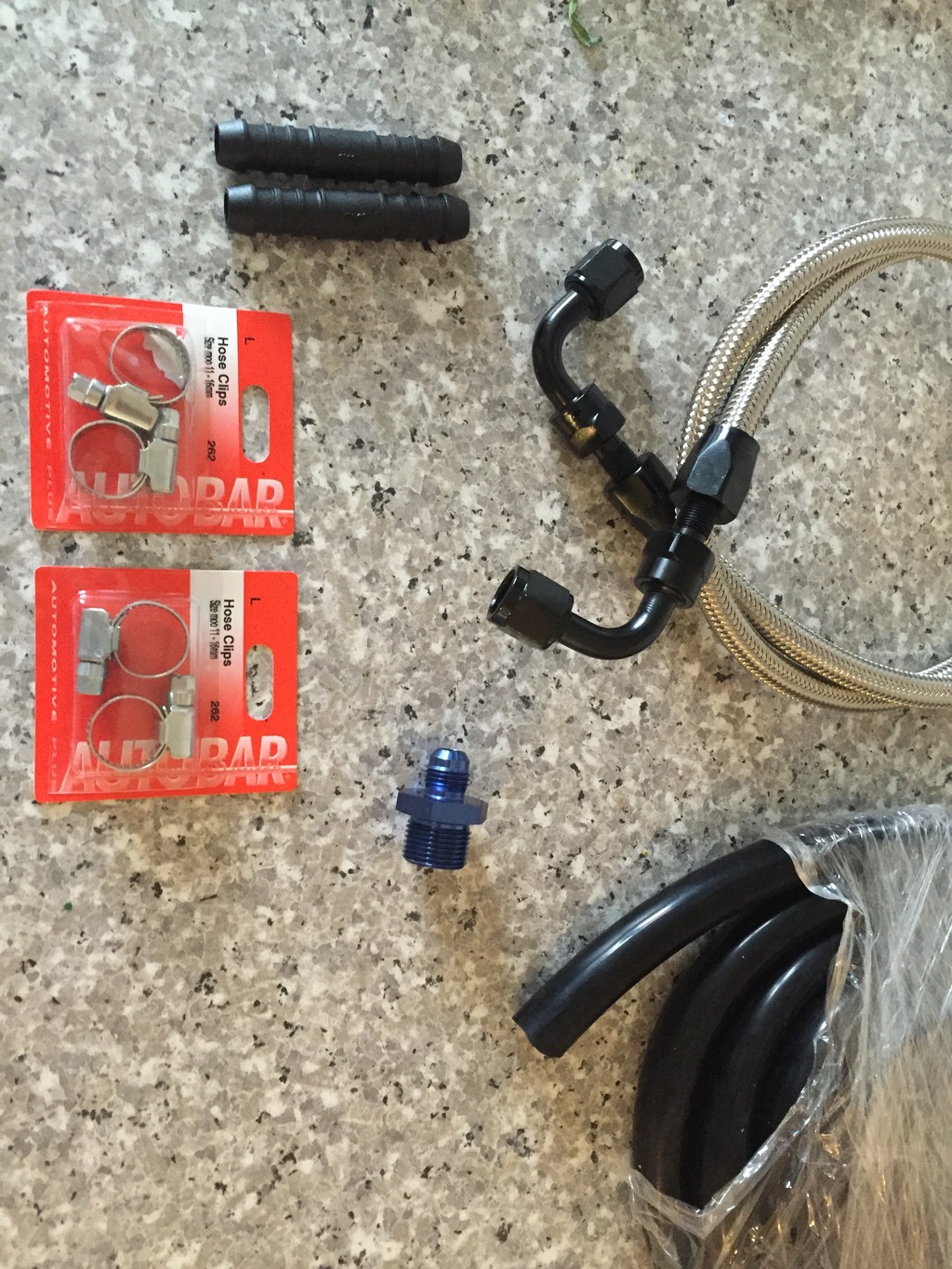
To do this install I needed.
X2 12mm straight pipe fittings
X2 12mm rubber caps
3 meters of vacuum hose
X2 M6 bolts and washers
To drain to sump your also will need.
X2 An6 90 degree hose fittings
1 metre of An6 braided hose
X1 An6 to M20 1.5 adapter
X1 Sump washer (supplied with oil filter)
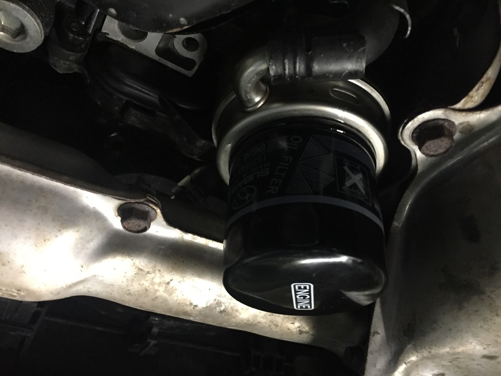
If you want to fit a to drain to sump pipe like I did your have to drain your engine oil.
Makes sense to do a full engine oil and oil filter service while your at it.
First thing I did was mount the catch can to the two bolt mounting points in the right hand strut wall using the two M6 bolts.
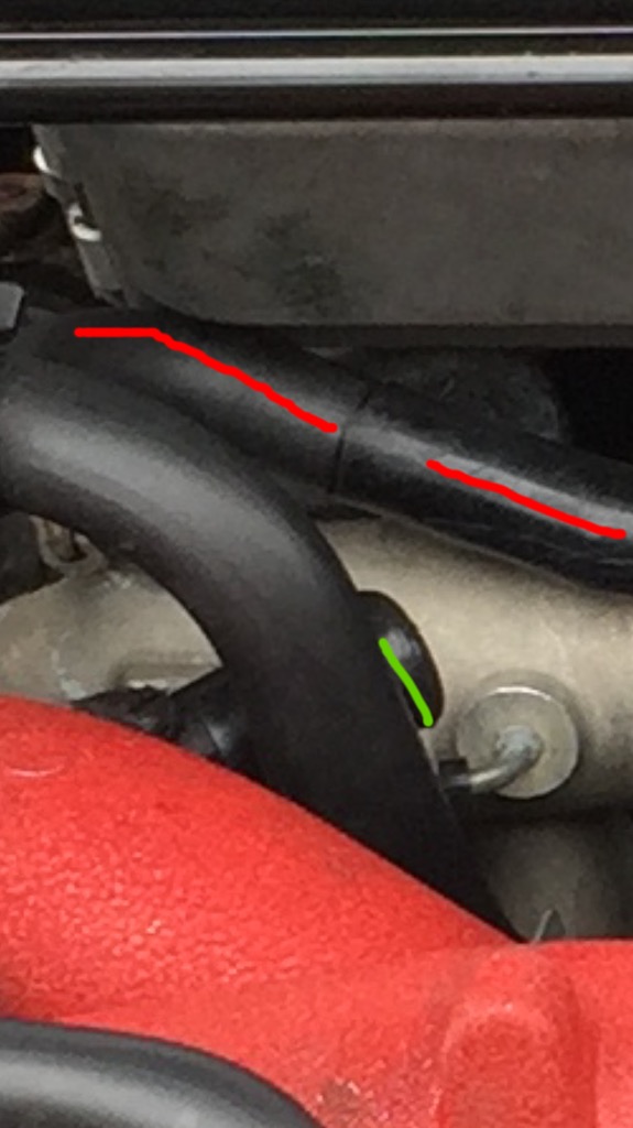
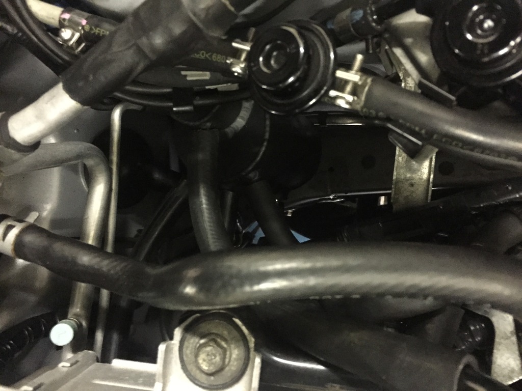
Next I had to seal up the crank case breather inlet on the turbo intake pipe that I wound no longer be using. I simply did this by putting a 12mm rubber cap over it.
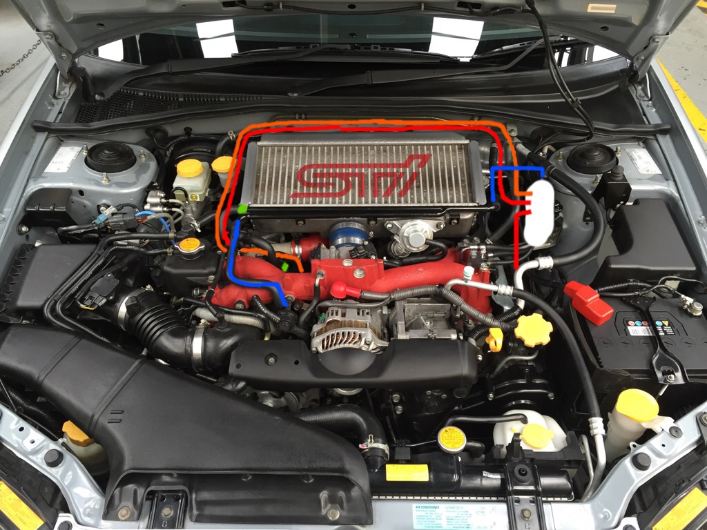
Marked by green line on photo.
Then as I would be using the metal head breather pipe that's mounted on the intercooler as part of my vent system, I needed to seal off the left hand port that is connected to the left hand head breather. Again I did this with a 12mm rubber cap.
Next I ran piping from the left hand head breather to the catch can.
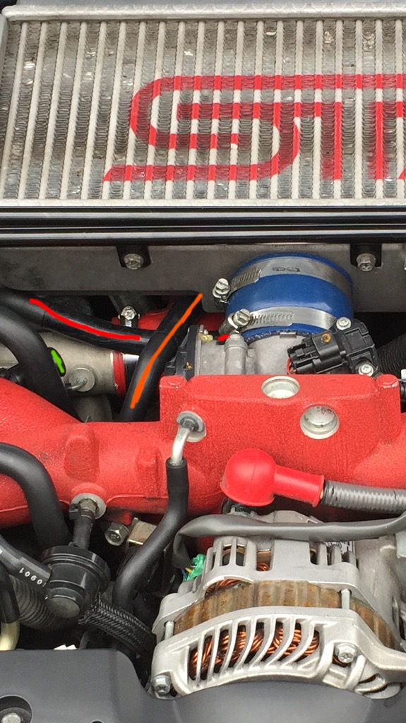
Using the original pipe work coming off the head breather I fitted a 12mm straight connection into it and extended the pipe routing under the intercooler into the catch can inlet port.
Marked by red line in photo.
Same method was used for the crankcase breather, I fitted a 12mm straight pipe connection to the original pipe to extend it to the catch can inlet port routing under the intercooler.
Marked by orange line in photo.
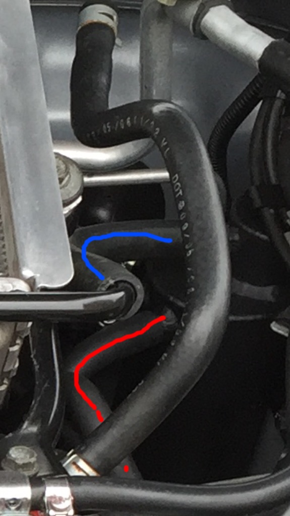
Then I did the the right hand side head breather by rerouting the original pipe to the catch can rather than to the metal breather pipe mounted to the intercooler.
Marked by red line in photo below.
Fitting the return to inlet pipe was done by running hose from the top vent on the catch can to the right hand port on the metal breather pipe mounted on the intercooler.
From here it would then use the original pipe work too make its way back to the turbo inlet pipe as it would on the original breather system.
Marked by blue line in photo.
As you can see the catch can and pipe work is hardly noticeable.
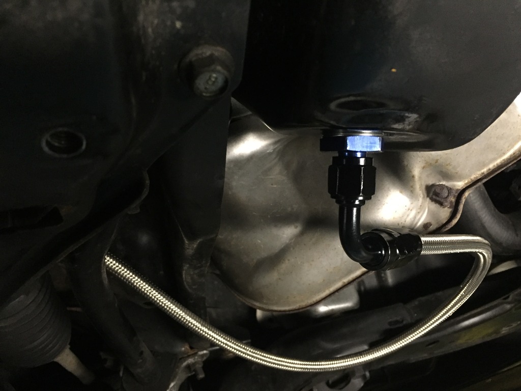
Next was to install the return to sump drain pipe.
To do this you first have to drain the engine oil as the return hose will replace your sump plug.
Im not going to go into detail on how to jack the car up and remove under trays and dispose of used oil ect.
Theres plenty of guides on that.
But I will mention some of more important points.
After draining oil remove your oil filter and replace with the new one. Making sure you apply a slight amount of fresh oil to rubber seal, filling the filter with some fresh oil also a good idea.
After all the oil has been drained the An6 to M20 adapter can be screwed into where the sump plug was. Remember to fit the sump crush washer.
Next the final An6 braided hose can be connected from the sump to the bottom drain connection on the catch can.
You can then fill your engine back up with the correct amount of your preferred brand of oil. Just remember to subtract what you added to the filter.
After filling the engine with the correct amount of oil it's best practice to disconnect the cam shaft position sensor under the alternator and crank the engine over a for a few seconds.
This will prime the system and make sure your oil filter, oil pump, turbo and bearings all have sufficient oil.
This will help reduce engine wear when you first start the car.
Once you have primed the system you can reconnect the cam shaft sensor and start the car, let the engine run for a few minutes then switch off.
After the engine oil has settled for 10 minutes or so recheck your oil level.
Make sure your car is on level ground otherwise your get a incorrect reading.
Don't worry if your check engine light is on, this is due to disconnecting the cam shaft position sensor.
This will go out after a few starts or you can speed things up by disconnecting your battery for 20 minutes, works a treat on my 07 hawk.
That's the install complete.
If you want to build a similar set up to mine you can see in the picture bellow I've made a colour coded map of where the catch can, pipes and rubber caps go. For ease of illustration I've shown the pipes going around the intercooler, but they actually routed under it.
White = catch can
Green= rubber caps
Red= head breathers
Orange = crankcase breather
Blue= vent back to inlet
This whole set up and install cost just under �100 (not including the oil and filter)
Really excellent thread. I'm debating doing this to my wagon, but not sure if I'm technically competent enough.
How hard was this to do? How long did it take?
Great write up, are you still happy with the setup mate? I have an RCM can which I intend on fitting soon, I will probably blank off rather than return to sump for ease of installation.
Great write up, are you still happy with the setup mate? I have an RCM can which I intend on fitting soon, I will probably blank off rather than return to sump for ease of installation.
I'm having an utter mare trying to fit mine. I've got a blob wagon and the only holes to attach the can to are holding the air con hose bracket. But to get the catch can to fit those I'm going to need to fabricate another bracket so the can doesn't foul anything.
I'm having an utter mare trying to fit mine. I've got a blob wagon and the only holes to attach the can to are holding the air con hose bracket. But to get the catch can to fit those I'm going to need to fabricate another bracket so the can doesn't foul anything.
As above. Richard Ellis 3 port baffled. I've also had issues that the standard RE can has 2 x 12 mm ports and 2 x 15mm ports whereas for this install (above) that I'm trying to copy it'd be easier if they were all 12mm. But I can get some reducers that will sort that out.
A catch can will always look a mess as the oil vapour mixes with condensation and over time it forms a gunky oil substance.
On a return system the oil drains back to the sump and doesn't seem to have that problem.
I'm kind of reluctant to agree with you there as it's mostly water type residue, but only because I'm now thinking of returning to sump as I'm sick of emptying the ******!
I seem do only drive it in nice weather lately and even then it's shortish journeys so not suprised with the condensation
A catch can will always look a mess as the oil vapour mixes with condensation and over time it forms a gunky oil substance.
On a return system the oil drains back to the sump and doesn't seem to have that problem.
When you installed the can itself did you have any issues with it catching on the pipework at the bottom of the passenger's suspension strut? This one circled in red:
Last edited by Cambs_Stuart; Jun 7, 2016 at 09:21 PM.
When you installed the can itself did you have any issues with it catching on the pipework at the bottom of the passenger's suspension strut? This one circled in red:
No it fits perfect. I mesured the space I had available and had the can made to my dimensions.
So, I have a different install in mind. Seems easier than that shown, so I'm wondering if there is a problem.
As I see it, why not connect the crank case breather to the existing return rail (red line) and leave the left hand head breather pipe untouched (blue line). The rails then join up in front of the intercooler, so just need to attach a pipe (green line) from the rail exit to the catch can (white), then run a pipe from the right hand head breather (yellow line) to T into the green line. Job done.
Is it not that simple? Why do I need any connection to the intake pipe?
Folks, I'm re-opening this thread (since it's very useful and has a link to the big NASIOC thread on catch can installs).
I'm reading on the NASIOC thread that the 2.5 litre block and the 2 litre are different in respect of crankcase ventilation and that there are 2 ports on the 2.5 litre crankcase.
I found these comments from 2011:
well, there are 2 crankcase vents on the 2.5L shortblock, and only 1 on the 2.0L heads. the guys that were capping this extra crankcase vent usually noticed an increase in blow-by and oil consumption. this second vent needs to be open and allowed to vent crank case pressure...
This from 2012:
The center port on the 2.5 block is unbaffled. This means raw oil (not oil vapor) is coming out of that port. You don't want to run that into a catch can unless you want to drain it every other day or do. I just went through all of this.
And then this:
the 2.5's are going to have the extra vents on the heads and crankcase that are all connected together. they are on a hard line though, so there isn't any reason to mess with those. if you leave that hard line'd set of vents alone, the rest can be connected the same as in the picture here.
This leaves me confused. I thought there was one location on the crankcase to attach a catch can (the one not far from the turbo). Where the hell is this other one? Apart from that, the PCV system for the crankcase and heads are not connected together at all. That's the whole point. They are separate systems and vent separately into the intake duct.
Last edited by David__H; Feb 20, 2018 at 10:06 PM.
After a lot of reading, two things are clear, in the ideal setup you have 2 catch cans, one for the crankcase and one for the heads. This is because the heads and crankcase will not be at the same pressure and teeing the lines together or putting them into the same catch can means that in the situation where either the heads or crankcase is under vacuum, the foul air from one system may be drawn into the other. With two cans, with two separate outlets to the intake duct (as per the stock arrangement), this can't happen.
The other thing I conclude is exactly how to connect up the crankcase catch can, as per the below picture. Essentially the catch can filters the outflow from the crankcase but the outlet piping retains a tee, connecting it to the PCV valve by the throttle body and to the intake duct. Again, this means the stock piping arrangement and PCV system is retained, you just added a catch can.
Of course the Americans get a big advantage over us since they have space to install two catch can side by side on the turret or firewall near the turbo. Unfortunately we have clutch fluid and brake fluid reservoirs round there and no space at all. There is definitely space to fit one on the nearside turret, as per the pictures at top of this thread. I wonder if a 2nd could be put by the fusebox just in front of that. It all adds a lot of pipework though.
I suppose what's really needed is a catch can with 2 separate halves to it with the crankcase connected to one side and the head breathers to the other...... And then twin outlets too.
Still wondering how much "positive" crankcase ventilation is really matters. If you give that up and just have crankcase ventilation, you just have a single catch can for crankcase and heads, vented to atmosphere. So simple and easy to do and there are folk doing just that with no problems reported (yet!!)
Last edited by David__H; Feb 20, 2018 at 10:32 PM.
these are my catch cans fixed to the bracket on the CAIK pipe. The black is connected to crank breather the smaller silver one connects to head breather. Both are baffled and connect back to turbo intake. A bit crude to look at but make use of available space. I've never found the heads produce much, if anything. The crank produces small amounts of gunge but heavy launch starts it traps al lot.<br/>Trev
Yeah I can see you have liberated some space with the CAIK. I'm surprised how small your catch can is for the heads. How did you know you were only going to get a little oil from the heads? Makes me think I should buy a single large can but only connect up the heads to start with and see what it collects. It could be that the heads aren't worth worrying about.
How do you drain these catch cans?
From the picture it looks like you've ditched the PCV valve and your return line for the crankcase can goes straight to the intake. Is that right?
I used to have a larger catch can for the heads but it always remained dry. I needed to make more room for a swirlpot so fitted what isn't much more than an inline filter, it is deep enough to trap anything. To drain I just detach it but never find anything. The crankcase can drains from an allen key plug at the bottom side.
The PCV valve is in place and operates as standard. The crankcase CC pipe connects just above the PCV connection and then runs back to turbo intake from the can. So in effect the breather system is as normal but interrupted by the catch cans.
Trev
Folks, I'm re-opening this thread (since it's very useful and has a link to the big NASIOC thread on catch can installs).
I'm reading on the NASIOC thread that the 2.5 litre block and the 2 litre are different in respect of crankcase ventilation and that there are 2 ports on the 2.5 litre crankcase.
I found these comments from 2011:
well, there are 2 crankcase vents on the 2.5L shortblock, and only 1 on the 2.0L heads. the guys that were capping this extra crankcase vent usually noticed an increase in blow-by and oil consumption. this second vent needs to be open and allowed to vent crank case pressure...
This from 2012:
The center port on the 2.5 block is unbaffled. This means raw oil (not oil vapor) is coming out of that port. You don't want to run that into a catch can unless you want to drain it every other day or do. I just went through all of this.
And then this:
the 2.5's are going to have the extra vents on the heads and crankcase that are all connected together. they are on a hard line though, so there isn't any reason to mess with those. if you leave that hard line'd set of vents alone, the rest can be connected the same as in the picture here.
This leaves me confused. I thought there was one location on the crankcase to attach a catch can (the one not far from the turbo). Where the hell is this other one? Apart from that, the PCV system for the crankcase and heads are not connected together at all. That's the whole point. They are separate systems and vent separately into the intake duct.
Just to try and clear up some of your confusion.
Yes there are two connections on the crankcase of most 2.5L crankcases but some of the earlier US 2.5's didn't have the central equalising connection.
Current blocks with "equalising" connection near the centreline
An early block without
One connects with pipework to both cylinder head covers equalising the pressure across the system. (centre line vent)
Pipes marked in yellow below
The pipe on the right (marked# 4) connects the cylinder head cover to the cross pipe fitted to the intercooler
The other crankcase vent (outboard) connects via a Y piece to the PCV valve (pipe #6) and to the turbo inlet pipe (pipe#3) - shown below in yellow
pipe#2 is the other head cover vent to intercooler cross pipe