PCV breather mod advice
 27 January 2007, 08:22 PM
#1
Scooby Regular
Thread Starter
Join Date: Jul 2006
Location: Poole, Dorset
Posts: 177
Likes: 0
Received 0 Likes
on
0 Posts
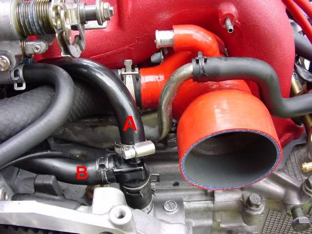
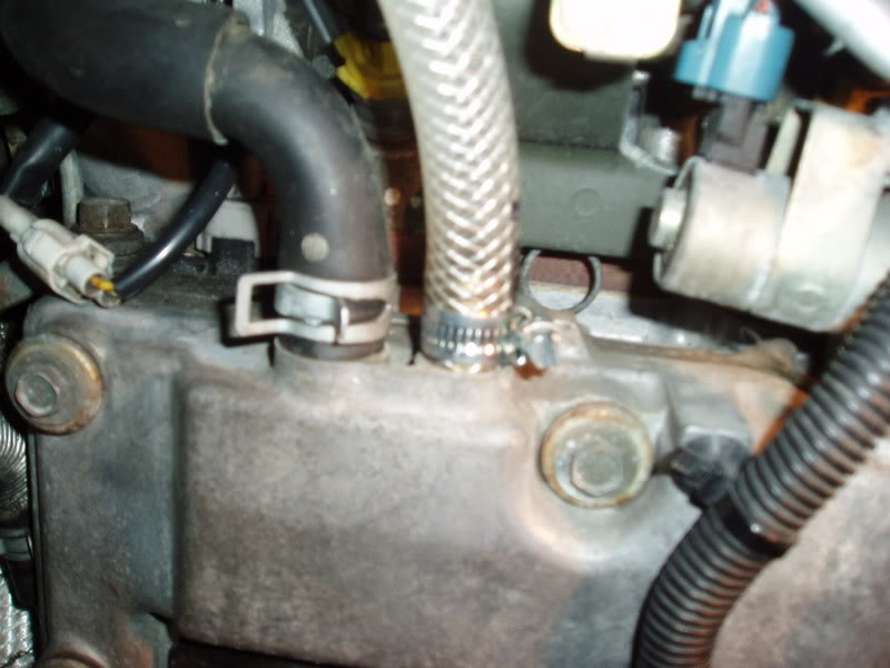
Can anyone help me out with advice on a breather mod I've been doing on my new age STI.... the attached is a photo of the PCV at the rear of the engine bay (turbo removed). I have vented pipe A to my catch can but pipe B is still running through to the underside of the throttle body. Question is, can I block off pipe B, remove the T piece althogether and then connect pipe A directly to the vent on the main block? This means there will be no venting back into the manifold, but will the car still run OK?
The other 2 vents I've run to the catch can are one head vent pipe on either side of the block. Basically there appears to be two similar sized 1/2" vent pipes coming off the block on each head. I've vented only the ones nearer the front of the engine... can the ones adjacent to them also be vented to the catch can? Sorry, would have posted a pic but forgot to take one today!
Cheers
Last edited by Jay_; 28 January 2007 at 09:17 PM.

 27 January 2007, 09:10 PM
#3
Scooby Regular
Thread Starter
Join Date: Jul 2006
Location: Poole, Dorset
Posts: 177
Likes: 0
Received 0 Likes
on
0 Posts
Neil... we've got small K&N style filters housed on the top of the catch cans... there's a pic on the Hants site under Technical. Mark's just posted a thread for the breather mod stage 1
28 January 2007, 09:28 PM
#5

I have performed the same mod and left the pcv connected. I read alot of threads re the pcv, whether to keep it or remove it.
I decided to leave it connected as opinion said that oil vapour generally leaves the block under positive pressure, (hard driving). When using hard accelleration the block has positive pressure and the pcv is blocked off, so no/or very little oil vapour enters the inlet tract reducing the octane rating of the fuel when using full throttle.
I hope that make sense
Andy
28 January 2007, 11:23 PM
#6

I have performed the same mod and left the pcv connected. I read alot of threads re the pcv, whether to keep it or remove it.
I decided to leave it connected as opinion said that oil vapour generally leaves the block under positive pressure, (hard driving). When using hard accelleration the block has positive pressure and the pcv is blocked off, so no/or very little oil vapour enters the inlet tract reducing the octane rating of the fuel when using full throttle.
I hope that make sense
Andy
I decided to leave it connected as opinion said that oil vapour generally leaves the block under positive pressure, (hard driving). When using hard accelleration the block has positive pressure and the pcv is blocked off, so no/or very little oil vapour enters the inlet tract reducing the octane rating of the fuel when using full throttle.
I hope that make sense
Andy
28 January 2007, 11:33 PM
#7
Scooby Regular

Join Date: Feb 2002
Location: Behind the 400BHP door :)
Posts: 1,403
Likes: 0
Received 0 Likes
on
0 Posts
I have done exactly what you suggested Jay.
Removed the PCV, and blanked with suitable bolt/plug.
Blocked 'B' off.
Vented 'A' to Catch Tank, along with the rocker vents.
Removed the PCV, and blanked with suitable bolt/plug.
Blocked 'B' off.
Vented 'A' to Catch Tank, along with the rocker vents.
Trending Topics
29 January 2007, 08:09 AM
#8
Scooby Regular

Join Date: Nov 2004
Location: In a 405 BHP/360 ft/lb P1 with SN superstar Sonic dog at my side!
Posts: 1,959
Likes: 0
Received 0 Likes
on
0 Posts
Looks rather like my engine! 
You will find that if you still keep pipe B connected to the PCV, you will not collect any resdue in the tank.
As Pickle says, plug the pipe, and the PCV hole up in the manifold and it works fine. RCM do it this way as well.
I have some drawings, will post them up later.
You will find that if you still keep pipe B connected to the PCV, you will not collect any resdue in the tank.
As Pickle says, plug the pipe, and the PCV hole up in the manifold and it works fine. RCM do it this way as well.
I have some drawings, will post them up later.
29 January 2007, 08:39 AM
#9
Scooby Regular
 29 January 2007, 08:54 AM
#10
Scooby Regular

Join Date: Mar 2003
Location: Scoobless :(
Posts: 1,210
Likes: 0
Received 0 Likes
on
0 Posts
The rocker vents are the plastic black pipe on top of each head. Run them seperately along with the crank breather to either atmosphere or a catch tank.
29 January 2007, 09:19 AM
#11
Scooby Regular
Thanks. Looks like we've done those already. There are two pipe on each side, we have run the ones closest to the front of the engine to the can.
What does the pipe behind it do ?
What does the pipe behind it do ?
29 January 2007, 09:47 AM
#12
Scooby Regular
Join Date: Nov 2004
Location: In a 405 BHP/360 ft/lb P1 with SN superstar Sonic dog at my side!
Posts: 1,959
Likes: 0
Received 0 Likes
on
0 Posts
Here you go-
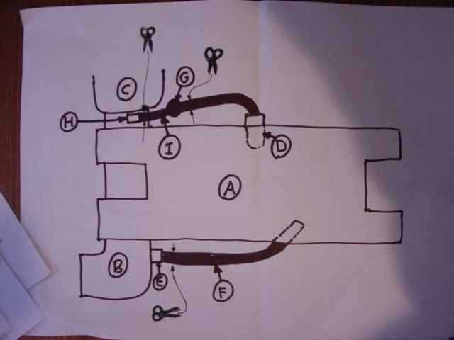
BEFORE
A is the inlet manifold
B is the inlet pipe
C is the turbo
D is the PCV valve
E is cam breather spigot on inlet pipe
F is cam breather pipe
G is crankcase vent tube
H is crankcase breather spigot on inlet pipe
I is crankcase breather pipe
the scissor points are where you need to cut the pipes leaving enough room to bung the pipes with a bolt or custom bung.
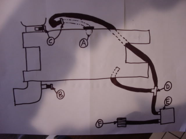
AFTER
A is a 1/4" BSP bung to replace the PCV valve
B is a bung for the cam breather spigot.
C are bungs for the crankcase breather spigot and the original pipe to the PVC
D is a T piece
E is the catch tank
F is a little filter
BEFORE
A is the inlet manifold
B is the inlet pipe
C is the turbo
D is the PCV valve
E is cam breather spigot on inlet pipe
F is cam breather pipe
G is crankcase vent tube
H is crankcase breather spigot on inlet pipe
I is crankcase breather pipe
the scissor points are where you need to cut the pipes leaving enough room to bung the pipes with a bolt or custom bung.
AFTER
A is a 1/4" BSP bung to replace the PCV valve
B is a bung for the cam breather spigot.
C are bungs for the crankcase breather spigot and the original pipe to the PVC
D is a T piece
E is the catch tank
F is a little filter
29 January 2007, 12:51 PM
#13
Scooby Regular
Thread Starter
Join Date: Jul 2006
Location: Poole, Dorset
Posts: 177
Likes: 0
Received 0 Likes
on
0 Posts
29 January 2007, 03:16 PM
#14
Scooby Regular
Join Date: Feb 2002
Location: Behind the 400BHP door :)
Posts: 1,403
Likes: 0
Received 0 Likes
on
0 Posts
Nope. All is fine.
As Mark says, I found that leaving the PCV valve on the Inlet manifold, I didn't get anything 'caught' in the Catch Tank.
Now, with the PCV removed, the Inlet Manifold is dry as a bone, and the Catch Tank collects all the condensation, and oil mist in a nice 'mayo goo'!!
You'll be suprised how quickly it fills up too!.
***Ps......The pipe 'F' in Marks diagram is the standard single pipe, which the rocker breathers have already been 'Tee'd' into. Just remove from Inlet Hose, and route to catch tank ***
***
As Mark says, I found that leaving the PCV valve on the Inlet manifold, I didn't get anything 'caught' in the Catch Tank.
Now, with the PCV removed, the Inlet Manifold is dry as a bone, and the Catch Tank collects all the condensation, and oil mist in a nice 'mayo goo'!!
You'll be suprised how quickly it fills up too!.
***Ps......The pipe 'F' in Marks diagram is the standard single pipe, which the rocker breathers have already been 'Tee'd' into. Just remove from Inlet Hose, and route to catch tank
***
Last edited by PICKLE; 29 January 2007 at 03:19 PM.
29 January 2007, 10:27 PM
#15
Scooby Regular
Thread Starter
Join Date: Jul 2006
Location: Poole, Dorset
Posts: 177
Likes: 0
Received 0 Likes
on
0 Posts
Great, thanks for the advice Pickle & Mark .... will block off the PCV as you suggest.
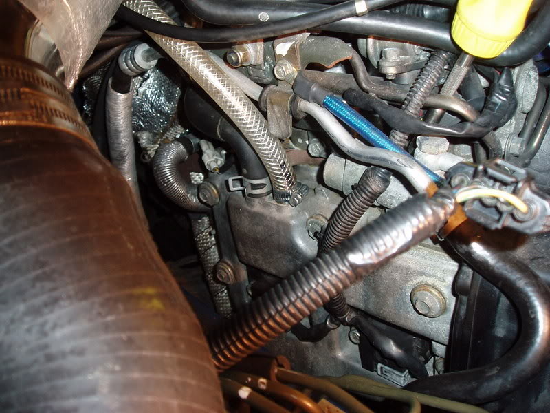
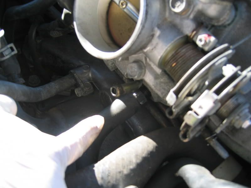
Back to my earlier query, now with pics of the left hand side of the engine with induction removed ... the other 2 vents I've run to the catch can are one head vent pipe on either side of the block. Basically there appears to be two similar sized 1/2" vent pipes coming off the block on each head. I've vented only the ones nearer the front of the engine (the clear/white braided hose)... can the ones adjacent to them also be vented to the catch can (stock black hose)? What is the black hose doing anyway!!?? Thanks
.... will block off the PCV as you suggest.Back to my earlier query, now with pics of the left hand side of the engine with induction removed
... the other 2 vents I've run to the catch can are one head vent pipe on either side of the block. Basically there appears to be two similar sized 1/2" vent pipes coming off the block on each head. I've vented only the ones nearer the front of the engine (the clear/white braided hose)... can the ones adjacent to them also be vented to the catch can (stock black hose)? What is the black hose doing anyway!!?? Thanks
31 January 2007, 07:42 PM
#17
Scooby Regular
Boing, can anyone confirm that we can 'vent' the 2nd pipe on the picture above. The one next to the clear pipe we have already vented.
19 September 2007, 11:27 PM
#19
Scooby Regular
iTrader: (1)
Join Date: Apr 2007
Location: Up-North Like!
Posts: 1,266
Likes: 0
Received 0 Likes
on
0 Posts
I'm just looking into this myself Mark, AFAIK you have got the right connection for your breather mod  I haven't traced the other pipe 100% but it appears to just link left bank to right bank as a balance pipe, it will allow un-equal pressure between the two sides to balance to reduce over all pressure.
I recieved my Hyperflow catch can today and planning to do the job this weekend. Going to link striaght off the IC breather pipe so I have both cam cover breather on one pipe and then connect straight to the crank breather bypassing the PCV and the return to intake, blocking both off. Then for breating, I'm just going to run the return pipe out of the catch can through the plastice under tray to the floor.
I'd just like to add that the hyperflow catch can has 9mm fittings so I guess that 9mm must be capable of flowing enough air to cope with the engine breather system
Would also just like to add that you need to bend the lower A/C pipe with the valve on to allow the can to sit in its location and the upper A/C pipe to allow fitting of the breather pipes. The can needs to mounted on the second whole by only using one bolt so I slight modification required to allow it to miss the rear of the headlight. And isn't it just typical that the battery I have doesn't suit the clamp that comes with the catch can kit.
I'm fitting it to a 2002 STi but it does say on the instructions, 01+ WRX.
Still, modding cars is never straight forward is it....................... ever
I haven't traced the other pipe 100% but it appears to just link left bank to right bank as a balance pipe, it will allow un-equal pressure between the two sides to balance to reduce over all pressure.I recieved my Hyperflow catch can today and planning to do the job this weekend. Going to link striaght off the IC breather pipe so I have both cam cover breather on one pipe and then connect straight to the crank breather bypassing the PCV and the return to intake, blocking both off. Then for breating, I'm just going to run the return pipe out of the catch can through the plastice under tray to the floor.
I'd just like to add that the hyperflow catch can has 9mm fittings so I guess that 9mm must be capable of flowing enough air to cope with the engine breather system
Would also just like to add that you need to bend the lower A/C pipe with the valve on to allow the can to sit in its location and the upper A/C pipe to allow fitting of the breather pipes. The can needs to mounted on the second whole by only using one bolt so I slight modification required to allow it to miss the rear of the headlight. And isn't it just typical that the battery I have doesn't suit the clamp that comes with the catch can kit.
I'm fitting it to a 2002 STi but it does say on the instructions, 01+ WRX.
Still, modding cars is never straight forward is it....................... ever
24 July 2008, 10:33 AM
#20
Scooby Newbie

Join Date: Jul 2008
Posts: 2
Likes: 0
Received 0 Likes
on
0 Posts
Not being rude.
Well, Is it really that important to install a catch can to the already crowded engine bay ?
Why can we just attacha long hose to PCV and run it to the deep under chassis and vent the blowby fumes out like a mini exhaust.
Just add a paper filter to the breathing inlet of the engine cover. Thats it. Simple.
Why get into collecting the messy oil ... what for ?? You may reply directly to fitsandy at g mail dot com
Thanks.
24 July 2008, 11:49 AM
#21
Scooby Regular

Join Date: Jun 2008
Location: Essex
Posts: 434
Likes: 0
Received 0 Likes
on
0 Posts
Does anyone vent engines to the exhaust system?? we do this a lot with big v8 drag race engines basicaly a slash cut tube inserted into the ehaust at an angle of about 45 degrees so the passage of the exhaust gasses creates a low presure area at the end of the tube which is connected too the crankcase vent and this positively draws the vapor ect from the motor into the ehaust, is there a reason not to do this?? bennifits i can see are no catch can no filters and positive purging of the crankcase??
when we got a bit more technical we fitted a small vacuum pump and pumped the cases clean this had a real good effect as there is a vacuum inside the cases, So no oil leaks, improved ring seal.and a neat instalation as it just needs one outlet from the motor all the others being blocked off
when we got a bit more technical we fitted a small vacuum pump and pumped the cases clean this had a real good effect as there is a vacuum inside the cases, So no oil leaks, improved ring seal.and a neat instalation as it just needs one outlet from the motor all the others being blocked off
 22 March 2015, 11:18 PM
#23

Ideally don't bother with changing any of it. The PCV system is there for a reason and won't work properly with pipes removed.
But to answer your question if you just want to connect a catch can then just get rid of the two way connector and put one pipe straight to the catch can. It will then work as a catch can should. If he has put B to the can and not blocked the PCV valve you would have a vacuum leak. By just using B and leaving A connected to the intake pipe you will get oily air going both ways and it's not worth bothering with as your catch can will get some dirty air and some will go into the engine.
However if you do vent the crank case to a can you will loose the PCV system which IMO (many will argue otherwise) is a bad idea.
Last edited by FMJ; 22 March 2015 at 11:22 PM.
24 March 2015, 06:49 PM
#27
Has he blocked the PVC valve below the throttle and the hole in the intake pipe just before the turbo? If so then yes that will allow pressure to go to the can... Not a setup I would recommend because I don't agree with the PCV delete but it's in line with what other people do.
24 March 2015, 08:42 PM
#30
Pipe B in that pic looks as it does standard and heads left and connects to the PCV which is a metal valve beneath the throttle.
This pic shows which way the hoses go as standard
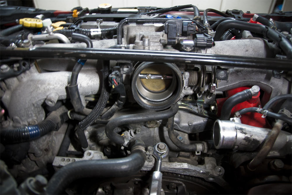
As long as both the PCV and the nipple on the inlet are plugged so they don't leak then that will be fine. Then the crank vent to the can. Then the can vented to atmosphere is what most people do.
This pic shows a PCV valve directly below the throttle
However IMO PCV is a good thing and should be kept. It should not be ditched and rerouted to fit a can. But that's just my opinion.
Last edited by FMJ; 24 March 2015 at 08:44 PM.