Starting again.... with a Hawkeye
 05 September 2011, 08:13 AM
#601

Harvey, I consider your test method flawed.
How do you compensate for air speed in the flowing pipe when measuring the vacuum from the sidewall? Higher flow (airspeed) will result in a lower measured pressure at the wall of the flowing pipe.
Its the most basic principle of aerodynamics, the one that keeps planes in the sky!!
Shaun - get that accel test done, we want faster cars on here not big dyno figures!
Very crudely you mount the manometer on your windscreen. This is the least satisfactory way and it will be subject to differing air flows and this is only a rough test. In fact unless you have a very efficient system you will not have enough manometer differential to mount the setup on your windscreen. Presumably you will be on the same piece of road running in both directions to get comparative results.
Your second option is to do the test on a rolling road where you only have the fan air which will be the same in both cases. This test only takes a few minutes and is a sure way to determine the efficiency of air inlet systems.
Most preferred method is to run the manometer in to the car in front of the passenger (as I described previously) who is going to take the differential pressure column reading anyhow. Same gear, same piece of road, same revs starting point and you soon know what system is better or which filter is more restrictive.
Sorry but for these reasons I don't accept the method is flawed except doing a rough check on the windscreen. It proves beyond doubt for me whatever air inlet system is least restrictive.
PS: If you wanted to get fancy about it you could mount your manometer on a hard board and let the passenger hold it as opposed to an improvised bit of tubing and long ruler.
Last edited by harvey; 05 September 2011 at 08:14 AM.
 05 September 2011, 10:04 AM
#602
Subaru Tuning Specialist

Join Date: Jun 2002
Location: 7.74 @179 mph 1/4 mile - road legal
Posts: 6,654
Likes: 0
Received 1 Like
on
1 Post
Harvey, your issue is not so much with the open reference end, its with the pressure/vacuum end where you connect into the turbo intake pipe. This is a high velocity area and in accordance with Bernoulli's principle, higher speed will result in lower pressure.
It is possible that a restriction would slow down the airspeed and result in a higher pressure reading, not a lower reading as you are expecting.
This will distort your results and it is the reason I say your test method is flawed.
It is possible that a restriction would slow down the airspeed and result in a higher pressure reading, not a lower reading as you are expecting.
This will distort your results and it is the reason I say your test method is flawed.
06 September 2011, 08:21 AM
#603
Harvey, your issue is not so much with the open reference end, its with the pressure/vacuum end where you connect into the turbo intake pipe. This is a high velocity area and in accordance with Bernoulli's principle, higher speed will result in lower pressure.
It is possible that a restriction would slow down the airspeed and result in a higher pressure reading, not a lower reading as you are expecting.
This will distort your results and it is the reason I say your test method is flawed.
It is possible that a restriction would slow down the airspeed and result in a higher pressure reading, not a lower reading as you are expecting.
This will distort your results and it is the reason I say your test method is flawed.
As the tests can be carried out on the same piece of road, same gear, same starting revs and so on it is a very repeatable experiment.
07 September 2011, 06:36 PM
#604
Scooby Regular

Thread Starter
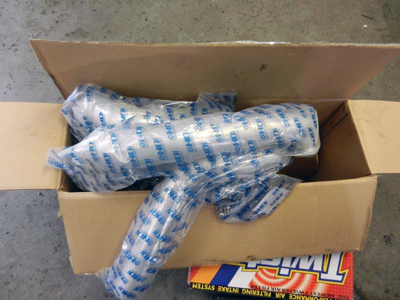
Hybrid GT2 Intercooler arrived at API today via Harvey Smith:

The "Twister" Inner Wing Kit also set aside at API ready for fitment:

Not long to go now!
The "Twister"
Inner Wing Kit also set aside at API ready for fitment:Not long to go now!

 . I meant the twister. I should know as I have one myself
") 08 September 2011, 09:27 AM
08 September 2011, 09:27 AM
#607
Former Sponsor


iTrader: (4)

Join Date: Jul 2003
Location: @Junc 12, M40 Warwicksh; 01926 614522 CV33 9PL -Use 9GX for Satnav. South Mids Alcatek ECu dealer
Posts: 6,377
Likes: 0
Received 3 Likes
on
3 Posts
[QUOTE=joz8968;10224412]I love receiving tuning goodies via post/courier - the excitement!.
Nahh !! no biggie that - happens every day here
Nahh !! no biggie that - happens every day here
12 September 2011, 10:55 PM
#609
Scooby Regular
Thread Starter
[Images removed due to bandwidth issues - will be sorted soon]
Three Day Modification Holiday - Day 1
So this was the start of the next extravagansa in the name of (hopefully) unleashing the potential of the LM450 Billet turbo. The latest round of supporting modifications!
Day 1 saw me booked in at API Engines.
Since the car had been bought originally from API, it only seemed fitting to return back to the fold at some point during it's modification life.
API have had previous involvement with my SPEC C, so they were a natural choice for getting involved again (and again lol) with the current Hawkeye project.
This time they were tasked with fitment of the Hybrid GT2 intercooler and supply and fitment of a inner wing induction kit. Something that is fairly run of the mill for a majority of their "drive in, drive out" engine build packages.
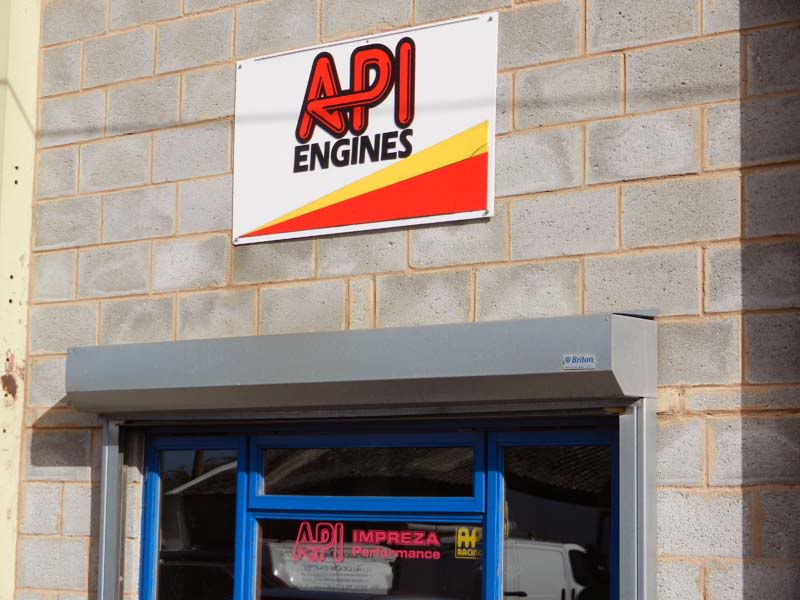
I'm sure many of you have been to API, but it really is an aladdins cave of everything Subaru.... and more.
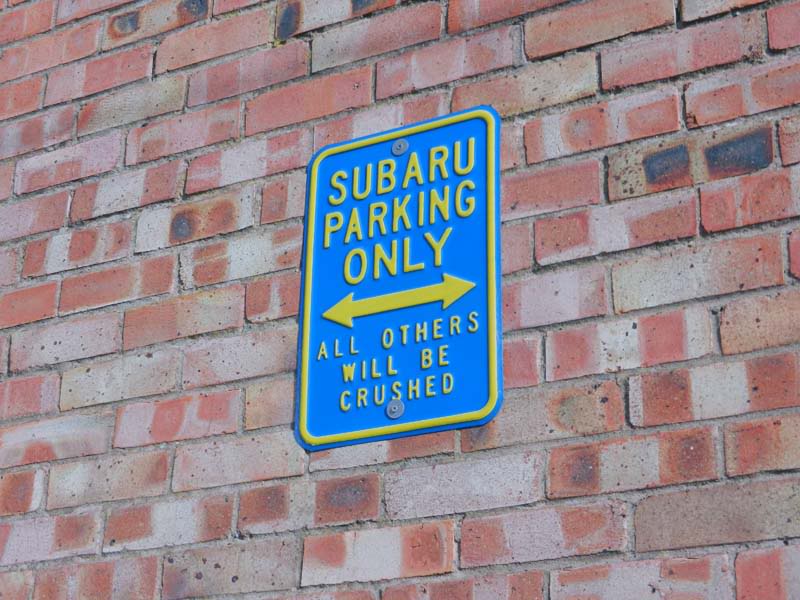
One of the big plaques outside on the wall, tends to draw your attention and brings a smile to your face.
I know I have mentioned this before earlier in this project thread, but I'm not sure I actually posted a picture of proof!? API actually have a 4WD DASTEK Rolling Road on-site. Something I'm not sure they publicise enough..... they should do, as there are not that many in the area!!
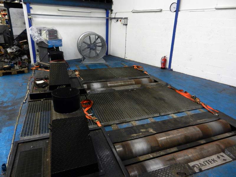
If you want a dyno run on your car, I'm sure they will oblige!
Anyway.... back to the reason for being at API:
So over the next couple of days API had been charged with fitting a Hybrid GT2 Intercooler, supplied by Harvey Smith, together with an API supplied Inner Wing Induction Kit.
One of the main reasons for having to change the inlet as part of this Intercooler fitment is for one main reason...... the OEM airbox has to be removed to allow the pipework from the left of the intercooler, to come through the same OEM airbox route, to join on to the turbo outlet. This takes air from the turbo outlet, through the intercooler (from the left to the right as you look at the intercooler) back up the righthand side and then into the plennum.
You will be able to see more about how and why further on.
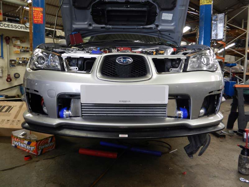
First things first was to remove the front bumper, which is fairly easy to do on the Hawkeye's snap fixtures.
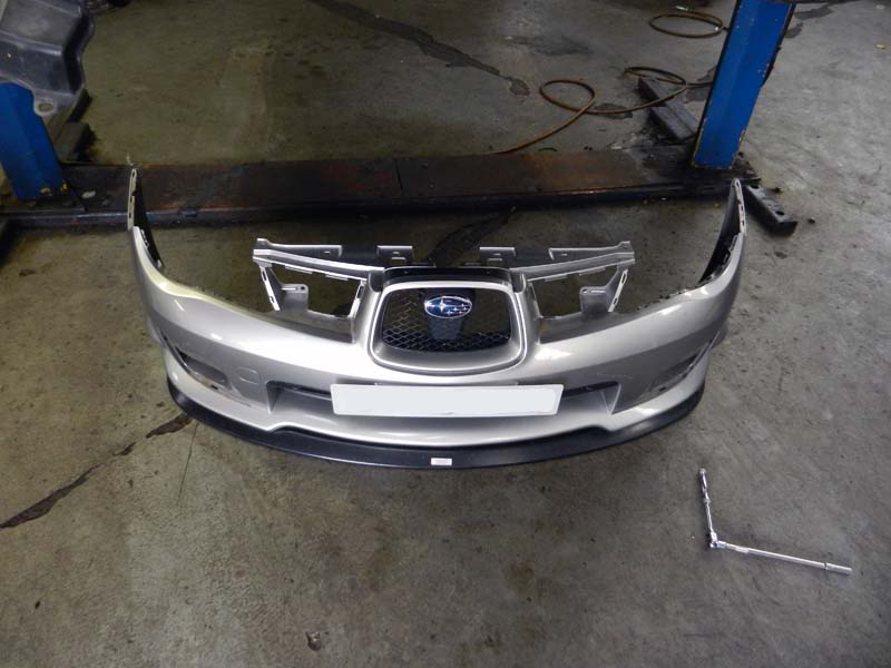
Car looks a bit "naked" with the bumper off!
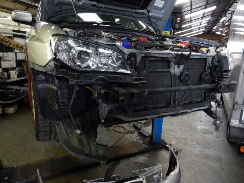
See that cross member tubing in front of the radiator...... that's exactly where the intercooler will end up!
Some intercooler kits remove the tow eye facility (far left location on the cross member) from this cross member (as they actually remove the cross member to fit). This specific install will be retaining that original toe eye location.
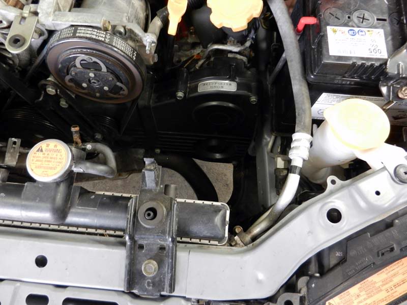
If you look at the far left of the picture you will also see the OEM resonator for the airbox (the black box just in front of the wheel). The "gut" feeling was, this is aiding (if you can call it that lol) a restriction in the air filter side of things. The air comes into this unit from the under bonnet snorkel, then gets pushed through this into the pipework up the inner wing and then into the airbox itself. This is part of the OEM system that will be removed.... namely because the intercooler pipework has to part fill this same path.
The task was to remove the various OEM "bits" from the engine bay.
We don't need these anymore (OEM TMIC and airbox).
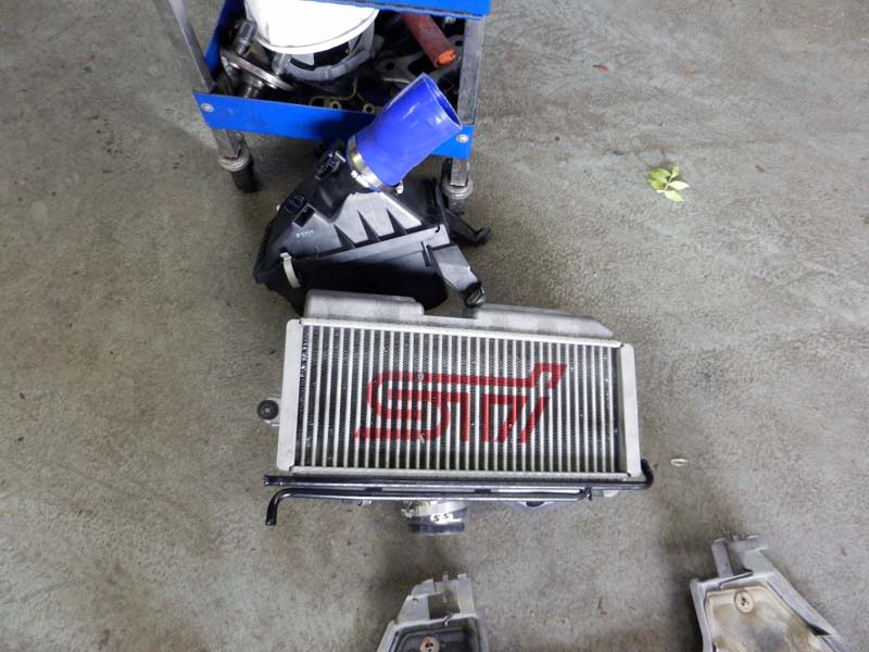
So with all the required "bits" removed, it was onto unpacking and looking to fit the Hybrid GT2 Intercooler.
Being totally honest here, I didn't know what to expect "quality" / "finish" wise with the Hybrid kit. I had never seen one before and I suspect you tend to assume that based on it's price point, it won't be as good a quality as most of the other kits costing over three times as much.
I was utterly surprised when the GT2 was out of the box..... like really surprised!
This intercooler core is big in regards to it's surface area.... but at the same time it feels light in weight.
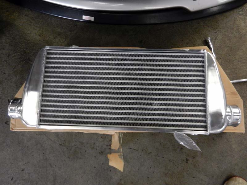
As you can hopefully see by this images... the quality is extremely good!
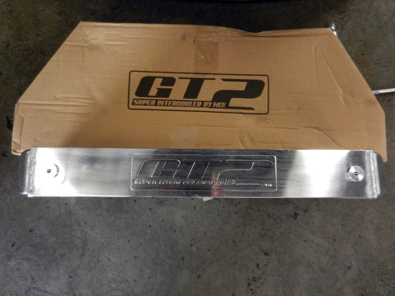
The all important GT2 core!

As I mentioned previously, this kit I have is actually the install pack for a Classic. Whilst the core is the same as the Newage kit, the pipework is slightly different. This is not a great problem for API, but does mean that the installation is not purely "bolt-on". Some parts of the pipework will need modification and for this reason alone, it was decided to allow two days to fit the FMIC and the Inner Wing Kit. Unfortunately there are no Newage kits in the UK presently, but as I have said, this is not a problem in reality.
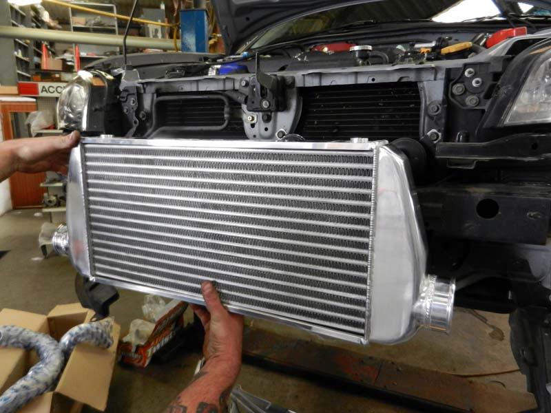
The start of this next process was certainly the part that needs to be done methodically, trying a "dry run" of the intercooler location to see what would be required with regards to pipe modifications.
Whilst this is not the right place for the core final location, it certainly puts in to perspective how big this intercooler is.
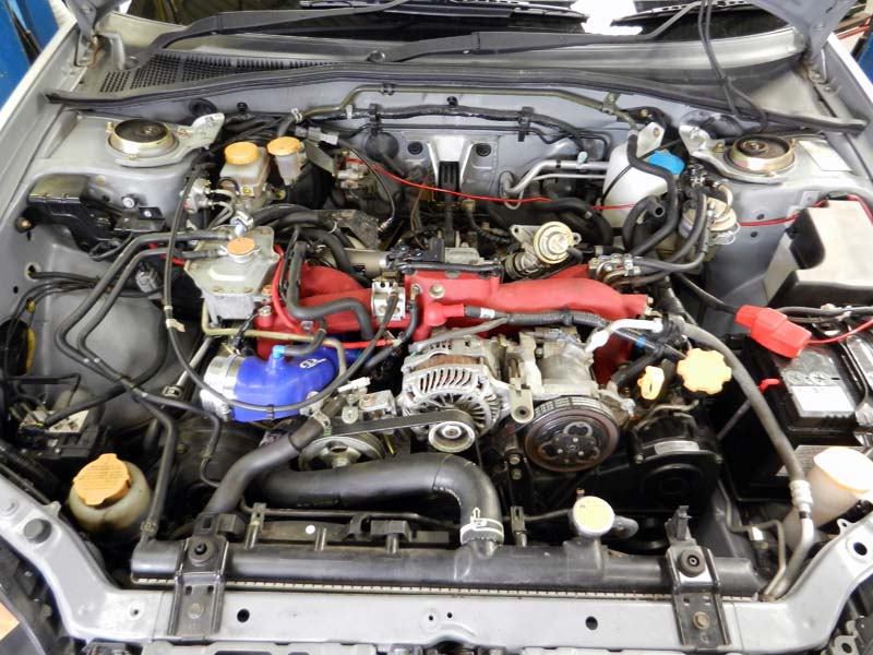
This is the righthand side of the engine bay, where the OEM coolant overflow bottle used to sit. This may require a different overflow bottle (as the TMIC pipework has to pass down here), but we will see what can be done about this later.
This is the lefthand side of the engine bay, where the original airbox sat, but again (the holes on the inner wing) will be used to pass the FMIC and inlet kit pipework through. This will require further modification to provide some extra space (cutting away the inner wing).
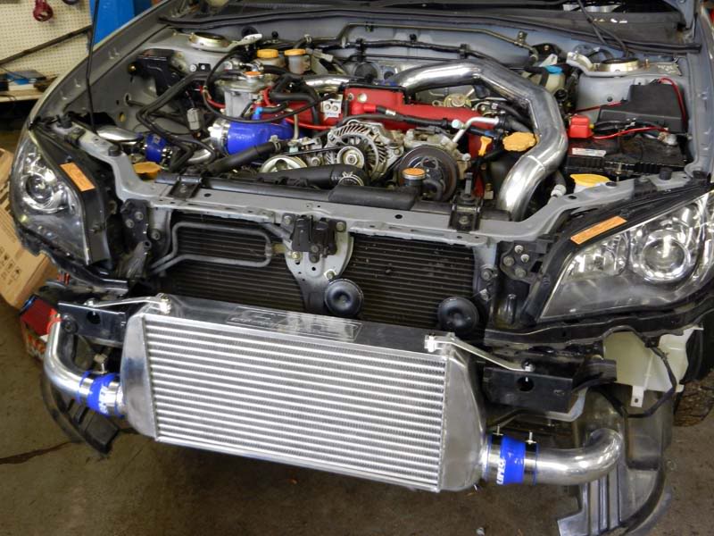
A few "bits" of frame and bracketry need to be removed from the front of the car first, to enable the intercooler to "slot" into place. It's a big core!
With the intercooler in it's final resting place, the pipework can be measured up and adjusted as required.
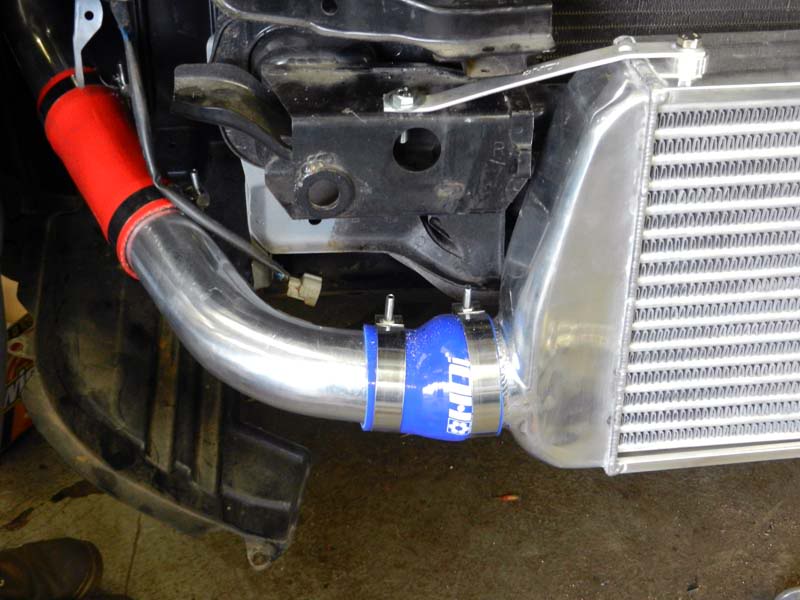
As you can see from this image below (front lefthand side), an extension is required (extra red silicon pipe) for fitment to a Hawkeye.
Rigthand side pipework in place.
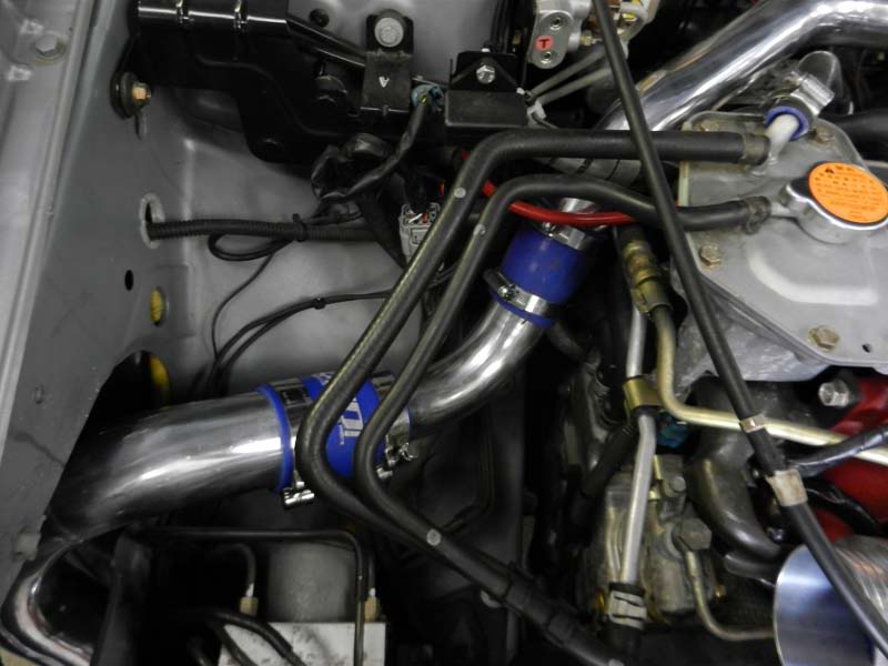
Modified inner wing (opened out) to take Hybrid pipework and eventual Inner Wing Induction kit.
Hybrid pipework in place from turbo and plennum.
Hybrid GT2 install nearly finished. API have decided to modify the righthand "joining" pipe (missing from this image) by TIG welding it.
At this point in time I actually left API, but whilst they were waiting for this specific pipe to be TIG welded, they started to cut the plastic bumper to accept the GT2 core.
Not a lot left to do for the Hybrid GT2 install in reality and the next step will be to look at the Inner Wing kit.
More pictures and information on this, when I return back to API tomorrow morning.
Three Day Modification Holiday - Day 1
So this was the start of the next extravagansa in the name of (hopefully) unleashing the potential of the LM450 Billet turbo. The latest round of supporting modifications!
Day 1 saw me booked in at API Engines.
Since the car had been bought originally from API, it only seemed fitting to return back to the fold at some point during it's modification life.
API have had previous involvement with my SPEC C, so they were a natural choice for getting involved again (and again lol) with the current Hawkeye project.
This time they were tasked with fitment of the Hybrid GT2 intercooler and supply and fitment of a inner wing induction kit. Something that is fairly run of the mill for a majority of their "drive in, drive out" engine build packages.
I'm sure many of you have been to API, but it really is an aladdins cave of everything Subaru.... and more.
One of the big plaques outside on the wall, tends to draw your attention and brings a smile to your face.
I know I have mentioned this before earlier in this project thread, but I'm not sure I actually posted a picture of proof!? API actually have a 4WD DASTEK Rolling Road on-site. Something I'm not sure they publicise enough..... they should do, as there are not that many in the area!!
If you want a dyno run on your car, I'm sure they will oblige!
Anyway.... back to the reason for being at API:
So over the next couple of days API had been charged with fitting a Hybrid GT2 Intercooler, supplied by Harvey Smith, together with an API supplied Inner Wing Induction Kit.
One of the main reasons for having to change the inlet as part of this Intercooler fitment is for one main reason...... the OEM airbox has to be removed to allow the pipework from the left of the intercooler, to come through the same OEM airbox route, to join on to the turbo outlet. This takes air from the turbo outlet, through the intercooler (from the left to the right as you look at the intercooler) back up the righthand side and then into the plennum.
You will be able to see more about how and why further on.
First things first was to remove the front bumper, which is fairly easy to do on the Hawkeye's snap fixtures.
Car looks a bit "naked" with the bumper off!
See that cross member tubing in front of the radiator...... that's exactly where the intercooler will end up!
Some intercooler kits remove the tow eye facility (far left location on the cross member) from this cross member (as they actually remove the cross member to fit). This specific install will be retaining that original toe eye location.
If you look at the far left of the picture you will also see the OEM resonator for the airbox (the black box just in front of the wheel). The "gut" feeling was, this is aiding (if you can call it that lol) a restriction in the air filter side of things. The air comes into this unit from the under bonnet snorkel, then gets pushed through this into the pipework up the inner wing and then into the airbox itself. This is part of the OEM system that will be removed.... namely because the intercooler pipework has to part fill this same path.
The task was to remove the various OEM "bits" from the engine bay.
We don't need these anymore (OEM TMIC and airbox).
So with all the required "bits" removed, it was onto unpacking and looking to fit the Hybrid GT2 Intercooler.
Being totally honest here, I didn't know what to expect "quality" / "finish" wise with the Hybrid kit. I had never seen one before and I suspect you tend to assume that based on it's price point, it won't be as good a quality as most of the other kits costing over three times as much.
I was utterly surprised when the GT2 was out of the box..... like really surprised!
This intercooler core is big in regards to it's surface area.... but at the same time it feels light in weight.
As you can hopefully see by this images... the quality is extremely good!
The all important GT2 core!
As I mentioned previously, this kit I have is actually the install pack for a Classic. Whilst the core is the same as the Newage kit, the pipework is slightly different. This is not a great problem for API, but does mean that the installation is not purely "bolt-on". Some parts of the pipework will need modification and for this reason alone, it was decided to allow two days to fit the FMIC and the Inner Wing Kit. Unfortunately there are no Newage kits in the UK presently, but as I have said, this is not a problem in reality.
The start of this next process was certainly the part that needs to be done methodically, trying a "dry run" of the intercooler location to see what would be required with regards to pipe modifications.
Whilst this is not the right place for the core final location, it certainly puts in to perspective how big this intercooler is.
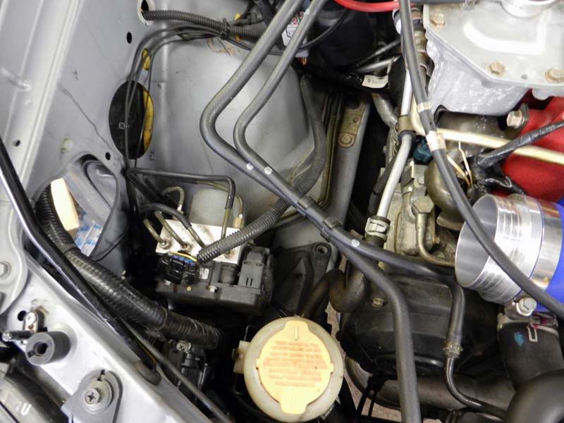
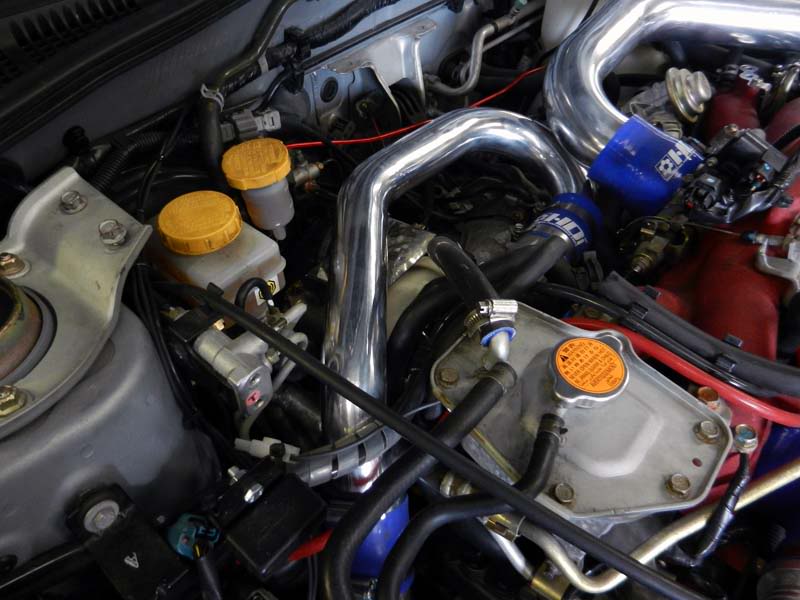
This is the righthand side of the engine bay, where the OEM coolant overflow bottle used to sit. This may require a different overflow bottle (as the TMIC pipework has to pass down here), but we will see what can be done about this later.
This is the lefthand side of the engine bay, where the original airbox sat, but again (the holes on the inner wing) will be used to pass the FMIC and inlet kit pipework through. This will require further modification to provide some extra space (cutting away the inner wing).
A few "bits" of frame and bracketry need to be removed from the front of the car first, to enable the intercooler to "slot" into place. It's a big core!
With the intercooler in it's final resting place, the pipework can be measured up and adjusted as required.
As you can see from this image below (front lefthand side), an extension is required (extra red silicon pipe) for fitment to a Hawkeye.
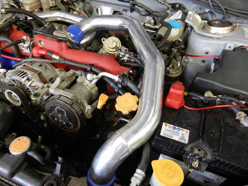
Rigthand side pipework in place.
Modified inner wing (opened out) to take Hybrid pipework and eventual Inner Wing Induction kit.
Hybrid pipework in place from turbo and plennum.
Hybrid GT2 install nearly finished. API have decided to modify the righthand "joining" pipe (missing from this image) by TIG welding it.
At this point in time I actually left API, but whilst they were waiting for this specific pipe to be TIG welded, they started to cut the plastic bumper to accept the GT2 core.
Not a lot left to do for the Hybrid GT2 install in reality and the next step will be to look at the Inner Wing kit.
More pictures and information on this, when I return back to API tomorrow morning.
Last edited by Shaun; 16 September 2011 at 12:56 PM.
12 September 2011, 11:34 PM
#610
i may sound a little thick here so please excuse me.
i have the same fmic and my pipe, the one in the last pic of yours, goes under the car at a really low and daft angle, making it sometimes a bit, how should we say, shut your eyes and hope it doesnt catch anything...
you mention it being tig welded, is this the pipe in question, that know runs up the side past the battery??? hope that makes sense.....if it is, i may just pay them a visit to do the same thing.....
13 September 2011, 06:46 AM
#611
Scooby Regular
Thread Starter
Thats one of the differences between the Classic and Newage kits. The Newage kit has the righthand pipe go down the back and under.
Although this is a Newage car, it's having the Classic kit fitted. This takes the conventional pipe route of over and down.
Although this is a Newage car, it's having the Classic kit fitted. This takes the conventional pipe route of over and down.
13 September 2011, 07:40 AM
#612
Scatty.
If the pipe running under the engine bed is too low it has not been fitted properly. No TIG welding required. Please PM me with your telephone contact details and we can advise you on fitting. Done properly you can refit the plastic undertray. This is purely a fitting issue.
Nice write up Shaun.
As Shaun stated he is fitting the Classic GT2 kit.
i may sound a little thick here so please excuse me.
i have the same fmic and my pipe, the one in the last pic of yours, goes under the car at a really low and daft angle,??? making it sometimes a bit, how should we say, shut your eyes and hope it doesnt catch anything...
you mention it being tig welded, is this the pipe in question, that know runs up the side past the battery??? hope that makes sense.....if it is, i may just pay them a visit to do the same thing.....
Nice write up Shaun.
As Shaun stated he is fitting the Classic GT2 kit.
13 September 2011, 07:55 AM
#613
Scooby Regular
Thread Starter
Just to underline..... the TIG welding of this specific bit of pipe is API's preferred method. You could of course silicon hose the new joint, but if you can keep these joints silicon hose free all the better. Again.... none of this needs to be done with the correct kit fitted (i.e. Newage kit for a Newage car, Classic kit for a Classic car).
However, it may transpire that we won't be able to get the TIG welding done for today (the guy that API use was in hospital yesterday, so we're hoping he is back in today). In this case API will use a silicon joiner as a temporary measure. Perfectly good and safe.
Thanks Harvey.
However, it may transpire that we won't be able to get the TIG welding done for today (the guy that API use was in hospital yesterday, so we're hoping he is back in today). In this case API will use a silicon joiner as a temporary measure. Perfectly good and safe.
Thanks Harvey.
13 September 2011, 08:14 AM
#614
Scooby Regular

Join Date: Feb 2009
Location: kempston bedford
Posts: 123
Likes: 0
Received 0 Likes
on
0 Posts
Hi Shaun
Looks very nice
Using the classic set up in the new age how does the pipe length compare ? Have you shortened the pipe length by going over the engine rather than going under the engine by any ?
Andy
Looks very nice
Using the classic set up in the new age how does the pipe length compare ? Have you shortened the pipe length by going over the engine rather than going under the engine by any ?
Andy
13 September 2011, 08:22 AM
#615
Scooby Regular
Thread Starter
Hi Andy,
Thanks.
Going "under" with the Newage kit, I believe shortens the pipe length slightly down the righthand side.
Thanks.
Going "under" with the Newage kit, I believe shortens the pipe length slightly down the righthand side.
13 September 2011, 05:17 PM
#617
Scooby Regular
iTrader: (2)

Join Date: Oct 2002
Location: oop north in a spec-c.Now sold and starting on a classic ra track/sprint/road car
Posts: 2,536
Likes: 0
Received 7 Likes
on
7 Posts
Well what did we say ages ago Shaun......down the slippery slope again...next will be engine internals.....joking apart this has been a good thread and glad to see you are keeping it sensible as for the front mount I'm glad you put some pictures up as I have decided to get the gt2 for my track car, harvey sent me some photos last week but there wasn't much detail in them your photo's have made my mind up.
13 September 2011, 05:53 PM
#618
we tried everything harvey, even phoned your chap when fitting it. think its the fact its a jdm that makes it sit lower. not ridiculously low, but no driving straight over bollards low....scoobyworld have managed to get it to sit slightly higher, but no way in this world on a jdm model will it sit so the undertray will go back on...impossible....
ps, i expect full lm450 power to be made now this is on....
ps, i expect full lm450 power to be made now this is on....
13 September 2011, 06:39 PM
#619
I assure you it is not impossible. Bring it to us and we will fit it properly and if we don't I will pay your petrol for getting to us. I don't know anybody that has fitted more of these than ourselves and on top of that we have rectified quite a few on both JDM and UK.
13 September 2011, 07:38 PM
#621
Scooby Regular
Thread Starter
Cliff,
David and his men were doing plenty of "rubbing" today.... believe me!
Gussy,
Don't you start!
That's it.... engine / power wise anyhow. I do like the modifying and this project type scenario, then I do actually driving the car tbh.... so who knows what will happen over the next 12 months. However, I will be trying my hardest to resist anything further.
I'm glad the Hybrid information has been useful to you..... that is one of the main reasons for this thread - to share the information I have gained and to discuss products!
Right I'm off to write-up todays escapades.
David and his men were doing plenty of "rubbing" today.... believe me!
Gussy,
Don't you start!
That's it.... engine / power wise anyhow. I do like the modifying and this project type scenario, then I do actually driving the car tbh.... so who knows what will happen over the next 12 months.
However, I will be trying my hardest to resist anything further.I'm glad the Hybrid information has been useful to you..... that is one of the main reasons for this thread - to share the information I have gained and to discuss products!
Right I'm off to write-up todays escapades.
13 September 2011, 09:25 PM
#622
Scooby Regular
Thread Starter
[Images removed due to bandwidth issues - will be sorted soon]
Three Day Modification Holiday - Day 2
Right... so yesterday had seen a majority of the "dummy build" completed for the Hybrid GT2 intercooler, by API.
Today's tasks by API were to:
* Complete the final fitment of the GT2
* Complete the bumper cut for the GT2
* Fit the induction kit
* Cold air ducting to induction kit
* Sort out the coolant expansion tank issue (this is only an issue because this is a Classic kit - the Newage kit comes with another expansion bottle)
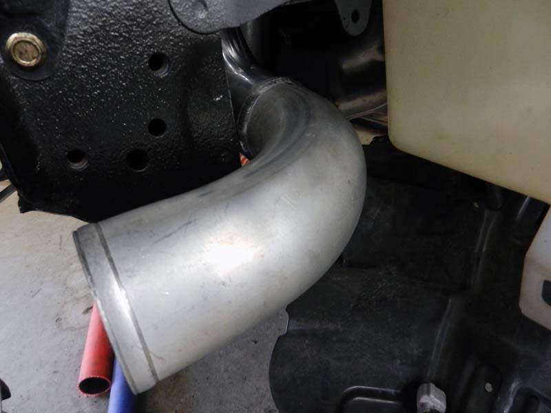
First off was to re-fit the intercooler pipe that was TIG welded (only just this morning).
This is the righthand pipe run from the intercooler to plenum (you can just see the weld ring off the bend). Again this was only needed because this pipework is for a Classic, rather than a Newage. Perfect fit now.
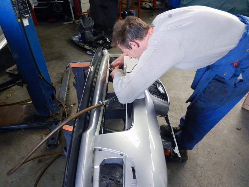
Next item of work was the "bit" you don't really want to get wrong if you're a fitter! Cutting up the front bumper!
API have done a number of these now, so as long as you have a methodical approach and take your time.... all's good (he says)!
To ensure the bumper fits back on snugly you need to remove part of the lower aperture (the lower mouth), along with unwanted "meat" from behind the foglamp covers.
The bit behind the foglamp covers is not as vital as the main bumper part, but all needs to be done properly in essence.
Using masking tape as a guide for the main bumper area, the parts to be removed are all masked to guide the cutting line. Then using an airsaw the offending parts are removed.
Don't be alarmed by the "ragged" look.... this is cleaned up at a later stage.
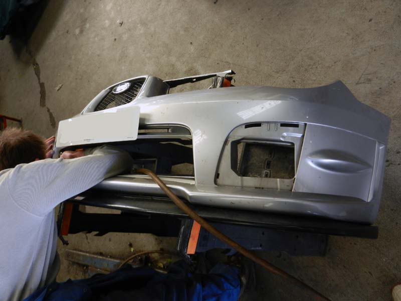
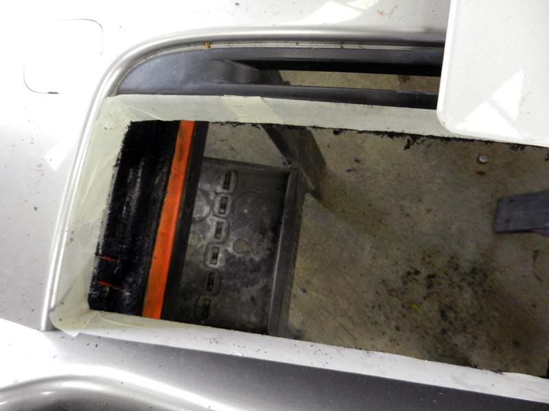
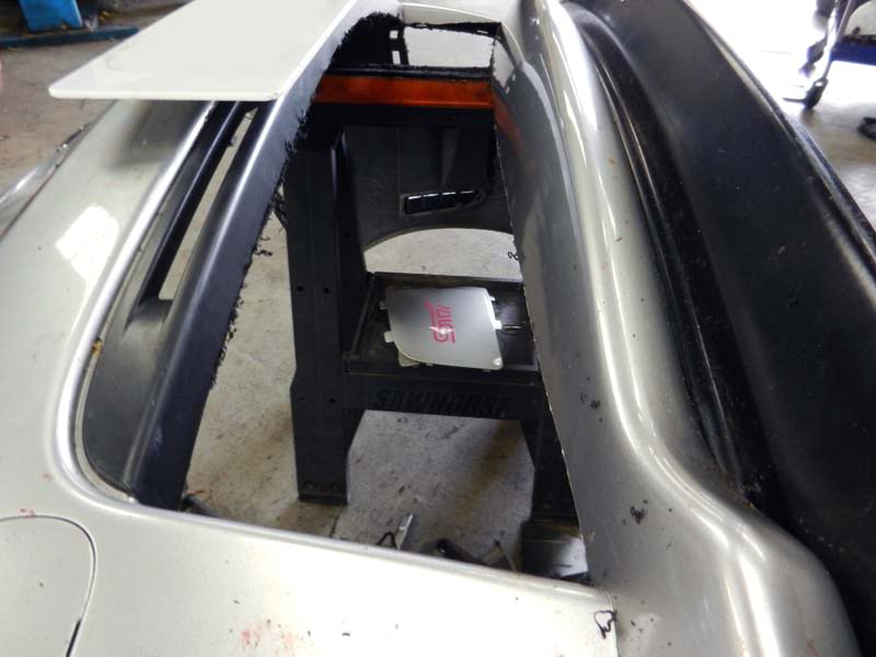
With the initial cut completed on the main bumper section, the "fat" is removed from behind the foglamp covers. This is required, primarily because of the FMIC pipework that sits behind these covers.
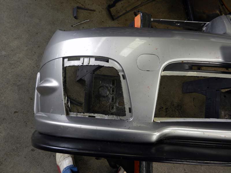
With the initial cut complete, the bumper is fixed back to the car to ensure everything fits as intended.
Once the fitment is correct it was then on to finishing the job and making it look more presentable.
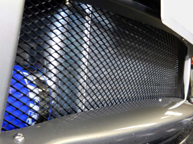
Something that API do is fit a custom mesh grill in front of the FMIC. When David told me about doing this I wasn't particularly eager. I don't really like grill kits as I think they look a bit cheap. David assured me it would look good, but also aids to protect my nice shiny new FMIC core from large stones hitting it and possibly causing damage. I went along with his judgement! lol
API use this mesh that is normally available from places like Halfords (shudder shudder).
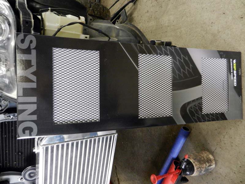
Cut to fit and held in place by appropriate fixings, has this effect on the same bumper grill area.
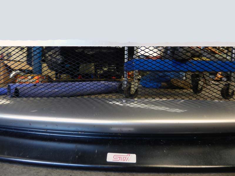
With the final fitting taking place, mesh in place and edges all cleaned up..... I was very impressed with the final result!
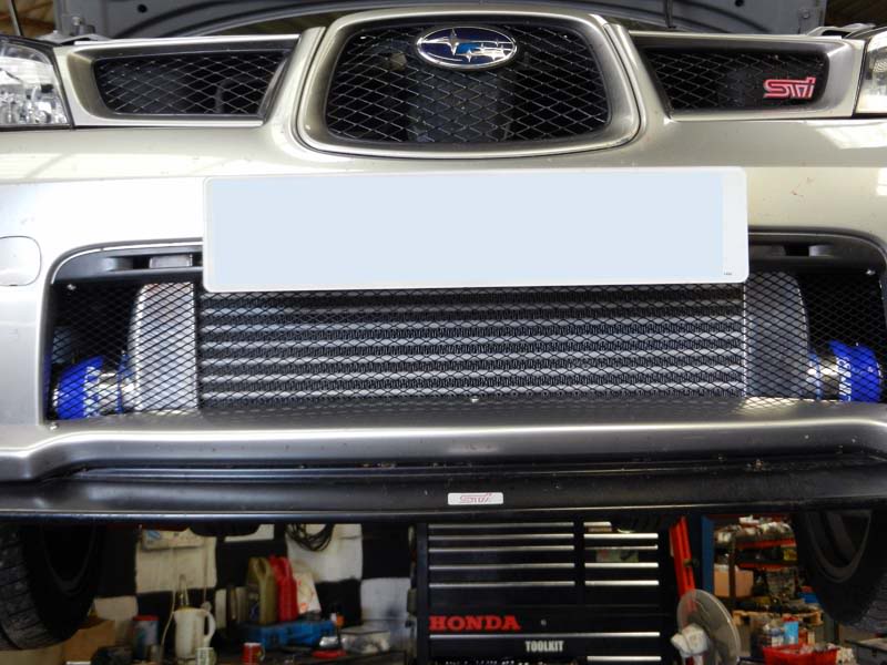
So that was the FMIC complete (nearly lol).....
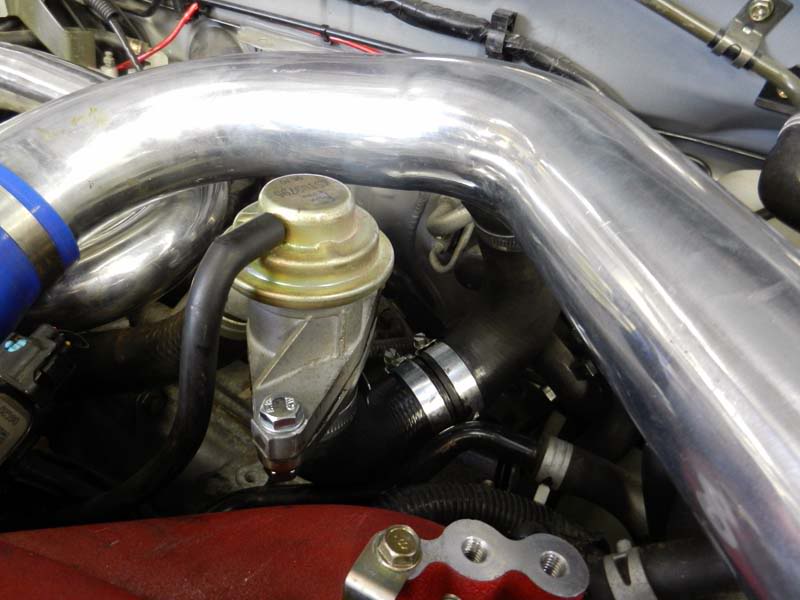
The Hybrid (like most IC's) have a take off that is used for the dump valve. I had already made my mind up that I wanted to retain the OEM dump valve.... no Carlos Fandango dump valves here please! The OEM one is more than enough for the job, so it's a waste of time replacing it imo.
Harvey supplies additional OEM Dump Valve flanges, so I had one of these sent through with the Hybrid GT2. This just enables you to mount the OEM dump valve to another plate, which will then slot in to another piece of silicon.
To save extending the OEM dump valve pipework, API manufactered another "U Shape" out of hose to attach the flange to the IC take off. That will do nicely.
The next step was to look at the Inner Wing Induction Kit......
With the time available this proved to be a step too far today. Whilst API could of made the inner wing induction kit pipework and filter fit, we just ran out of time to do it properly and neatly.
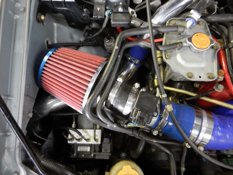
Plan B was pulled into reality...... an engine bay induction kit. Got to be honest here as this was not my preferred option, but something needed to be done to enable the car to be mapped tomorrow.
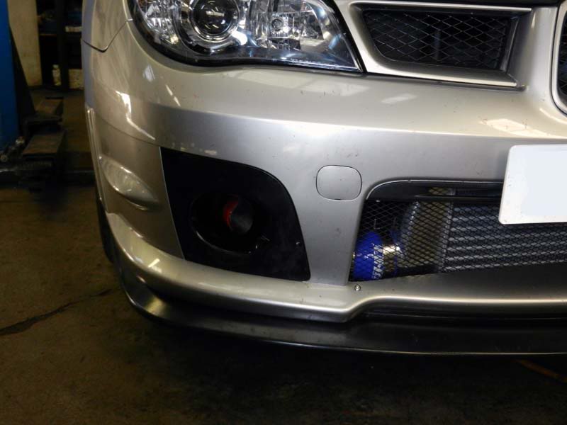
Theoretically once the car is moving, there should be enough air circulation around the engine bay to ensure cool air is sucked in by the filter. To further aid this (whilst I was looking around the API workshop with David looking for something else - we found) API fitted a WRX type foglamp cover on the side of the airfilter.
The inner wing had already been "opened up" for the intended inlet kit pipework and since the corner under panel had been retained, it acted as a nice ram box, directing the air up to the airfilter. Not air tight, but it will certainly help. API would of fitted some kind of formal ducting pipe to the opening within the inner wing (to the air filter), but unfortunately nothing was available at the workshop to do this right now.
The end result was good enough considering the constraints and was a certain "get out of jail" card for the time being.
The final problem to resolve, was that of relocated the original OEM coolant overflow tank.... or fitting another replacement one.
Again just to underline this issue.... this is only because we are fitting a Classic GT2 kit instead into a Newage car, instead of the preferred Newage kit. Basically you run out of space on the Newage car. The Newage kit contains a new overflow tank.... since the Classic does not need this relocating, it doesn't have one supplied.
Although this would prove to be a very temporary solution, API found something that would fill this immediate requirement. Especially so late in the day.
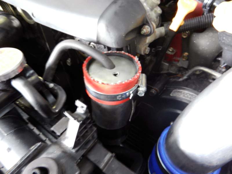
It will do it's job until API fit a proper alloy expansion tank.
So that was it.
A couple of hiccups were had along the way and some things still need some further work, but all in all API did a sterling job.
I would personally like to thank API for all their work over the past couple of days. Even when things didn't go to plan (does it ever!) they managed to get past that and ensure I could drive out this evening.
So a couple of things to do for a future API visit are:
*Properly duct from the front foglamp cover to the induction kit
*Enclose the induction kit within the engine bay
*Fabricate and fit a bigger expansion tank
The next instalment will be the remap tomorrow at Tracktive Solutions!
Three Day Modification Holiday - Day 2
Right... so yesterday had seen a majority of the "dummy build" completed for the Hybrid GT2 intercooler, by API.
Today's tasks by API were to:
* Complete the final fitment of the GT2
* Complete the bumper cut for the GT2
* Fit the induction kit
* Cold air ducting to induction kit
* Sort out the coolant expansion tank issue (this is only an issue because this is a Classic kit - the Newage kit comes with another expansion bottle)
First off was to re-fit the intercooler pipe that was TIG welded (only just this morning).
This is the righthand pipe run from the intercooler to plenum (you can just see the weld ring off the bend). Again this was only needed because this pipework is for a Classic, rather than a Newage. Perfect fit now.
Next item of work was the "bit" you don't really want to get wrong if you're a fitter! Cutting up the front bumper!
API have done a number of these now, so as long as you have a methodical approach and take your time.... all's good (he says)!
To ensure the bumper fits back on snugly you need to remove part of the lower aperture (the lower mouth), along with unwanted "meat" from behind the foglamp covers.
The bit behind the foglamp covers is not as vital as the main bumper part, but all needs to be done properly in essence.
Using masking tape as a guide for the main bumper area, the parts to be removed are all masked to guide the cutting line. Then using an airsaw the offending parts are removed.
Don't be alarmed by the "ragged" look.... this is cleaned up at a later stage.
With the initial cut completed on the main bumper section, the "fat" is removed from behind the foglamp covers. This is required, primarily because of the FMIC pipework that sits behind these covers.
With the initial cut complete, the bumper is fixed back to the car to ensure everything fits as intended.
Once the fitment is correct it was then on to finishing the job and making it look more presentable.
Something that API do is fit a custom mesh grill in front of the FMIC. When David told me about doing this I wasn't particularly eager. I don't really like grill kits as I think they look a bit cheap. David assured me it would look good, but also aids to protect my nice shiny new FMIC core from large stones hitting it and possibly causing damage. I went along with his judgement! lol
API use this mesh that is normally available from places like Halfords (shudder shudder).
Cut to fit and held in place by appropriate fixings, has this effect on the same bumper grill area.
With the final fitting taking place, mesh in place and edges all cleaned up..... I was very impressed with the final result!
So that was the FMIC complete (nearly lol).....
The Hybrid (like most IC's) have a take off that is used for the dump valve. I had already made my mind up that I wanted to retain the OEM dump valve.... no Carlos Fandango dump valves here please! The OEM one is more than enough for the job, so it's a waste of time replacing it imo.
Harvey supplies additional OEM Dump Valve flanges, so I had one of these sent through with the Hybrid GT2. This just enables you to mount the OEM dump valve to another plate, which will then slot in to another piece of silicon.
To save extending the OEM dump valve pipework, API manufactered another "U Shape" out of hose to attach the flange to the IC take off. That will do nicely.
The next step was to look at the Inner Wing Induction Kit......
With the time available this proved to be a step too far today. Whilst API could of made the inner wing induction kit pipework and filter fit, we just ran out of time to do it properly and neatly.
Plan B was pulled into reality...... an engine bay induction kit. Got to be honest here as this was not my preferred option, but something needed to be done to enable the car to be mapped tomorrow.
Theoretically once the car is moving, there should be enough air circulation around the engine bay to ensure cool air is sucked in by the filter. To further aid this (whilst I was looking around the API workshop with David looking for something else - we found) API fitted a WRX type foglamp cover on the side of the airfilter.
The inner wing had already been "opened up" for the intended inlet kit pipework and since the corner under panel had been retained, it acted as a nice ram box, directing the air up to the airfilter. Not air tight, but it will certainly help. API would of fitted some kind of formal ducting pipe to the opening within the inner wing (to the air filter), but unfortunately nothing was available at the workshop to do this right now.
The end result was good enough considering the constraints and was a certain "get out of jail" card for the time being.
The final problem to resolve, was that of relocated the original OEM coolant overflow tank.... or fitting another replacement one.
Again just to underline this issue.... this is only because we are fitting a Classic GT2 kit instead into a Newage car, instead of the preferred Newage kit. Basically you run out of space on the Newage car. The Newage kit contains a new overflow tank.... since the Classic does not need this relocating, it doesn't have one supplied.
Although this would prove to be a very temporary solution, API found something that would fill this immediate requirement. Especially so late in the day.
It will do it's job until API fit a proper alloy expansion tank.
So that was it.
A couple of hiccups were had along the way and some things still need some further work, but all in all API did a sterling job.
I would personally like to thank API for all their work over the past couple of days. Even when things didn't go to plan (does it ever!) they managed to get past that and ensure I could drive out this evening.
So a couple of things to do for a future API visit are:
*Properly duct from the front foglamp cover to the induction kit
*Enclose the induction kit within the engine bay
*Fabricate and fit a bigger expansion tank
The next instalment will be the remap tomorrow at Tracktive Solutions!
Last edited by Shaun; 16 September 2011 at 12:58 PM.
14 September 2011, 12:14 PM
#623
Scooby Regular
Thread Starter
Full details to come as I'm booked on Powerstations Rollers later, for a comparison run...
Mapping has appeared to have gone well (still at Tracktive now).
I will explain this all later, but the data hungry amongst you (and of course mappers) should appreciate what a MAF airflow of 382gs "should" relate to (on MegaROM standard MAF housing) power wise.
Let's hope this translates to the dyno.
14 September 2011, 07:29 PM
#624
Scooby Regular
iTrader: (3)
Join Date: Feb 2009
Location: Glasgow
Posts: 569
Likes: 0
Received 0 Likes
on
0 Posts
I am itching to see the results!
I too am just about to embark on my final mapping session to see what Laterals Headers, a FMIC and induction kit will do for my MD321T on my 2.5 Hawkeye.
I too am just about to embark on my final mapping session to see what Laterals Headers, a FMIC and induction kit will do for my MD321T on my 2.5 Hawkeye.
14 September 2011, 09:09 PM
#625
Subaru Tuning Specialist
Join Date: Jun 2002
Location: 7.74 @179 mph 1/4 mile - road legal
Posts: 6,654
Likes: 0
Received 1 Like
on
1 Post
Good work Shaun
It will be interesting to compare the deltadash accel times to my similar spec car (Spec C, 321T, 650cc, CAIK, TMIC) with the main difference being that you are taking warm air and cooling it, I'm taking cold air and warming it
It will be interesting to compare the deltadash accel times to my similar spec car (Spec C, 321T, 650cc, CAIK, TMIC) with the main difference being that you are taking warm air and cooling it, I'm taking cold air and warming it
Last edited by Andy.F; 14 September 2011 at 09:10 PM.
15 September 2011, 12:01 AM
#626
Scooby Regular
Thread Starter
Apologies guys as I have been getting all the days "detail" up each night.....
I've only just got in from doing a load of logging and have tons of data to divulge. I'm not going to get chance to do that now, so will return to this tomorrow night and get everything up.
What I can say is that there is more power and quicker acceleration times to report for tomorrow. I'm chuffed with the results to be honest and I think there is more to come out of fettling this set-up.... but more on that and today's detail, later tomorrow.
Andy,
Airflow is now getting close to the MAF limit.... 4.94v's and 388g/s was logged tonight in nice cool temps. Thanks for the info you provided me last week on how you "got on" in this area.
I've only just got in from doing a load of logging and have tons of data to divulge. I'm not going to get chance to do that now, so will return to this tomorrow night and get everything up.
What I can say is that there is more power and quicker acceleration times to report for tomorrow.
I'm chuffed with the results to be honest and I think there is more to come out of fettling this set-up.... but more on that and today's detail, later tomorrow.Andy,
Airflow is now getting close to the MAF limit.... 4.94v's and 388g/s was logged tonight in nice cool temps. Thanks for the info you provided me last week on how you "got on" in this area.
 look forward to seeing the figures
15 September 2011, 02:25 PM
look forward to seeing the figures
15 September 2011, 02:25 PM
#628
Subaru Tuning Specialist
Join Date: Jun 2002
Location: 7.74 @179 mph 1/4 mile - road legal
Posts: 6,654
Likes: 0
Received 1 Like
on
1 Post
Maf voltage and calculated flow doesn't mean that much after you relocate the maf sensor, you can max them out with 430bhp or they can read to 1000+bhp depending on location and tube size.
15 September 2011, 03:00 PM
#629
Scooby Regular
Thread Starter
The MAF pipe is the same diameter as OEM and location as near as damn it the same.
My reference to the MAF voltage and airflow was in regard to it's current location and OEM size MAF pipe. Hopefully being as comparative against OEM as possible without rescaling the MAF.
15 September 2011, 03:13 PM
#630
Scooby Regular
Join Date: Feb 2009
Location: kempston bedford
Posts: 123
Likes: 0
Received 0 Likes
on
0 Posts
Andy