
Bolt-on 360 bhp x 330lbft: Phase one started.

Looks to me as though they will fit Graham, that adaptor kit is virtually identical to one i have just designed for the same injector/rail. You will also need longer screws to secure the cap. I use 30mm with my kit although 25mm look as though they will be more suitable for that top collar.
You haven't left the o-ring for the 440cc injector in the chamber have you?

You haven't left the o-ring for the 440cc injector in the chamber have you?

Scooby Regular
Joined: Jan 2001
Posts: 6,812
Likes: 1
From: West Sussex
I used the Samco 'Y' I had from the MY97 UK IC
The 'Y' is all one piece where as the STI has a metal 'Y' and a samco linking the 'Y' to the turbo.
The 550 denso's look the same as mine and the adaptors are identical
Is the little adaptor a tight fit?
I had a small 'O' ring behind the pintle cap and the adaptor was quite loose. Cranked the engine over and fuel pi$$ed past the 'O' ring into the bore
Fitted a new fatter seal and all was well

Scooby Regular
Joined: Apr 2003
Posts: 1,541
Likes: 0
From: Cambridgeshire
Before I actually tried pressurising with fuel I removed the rails, made up a couple of rail attachments and pressure tested them all with compressed air - which proved to be a bonus as I tested each injector with a +12vdc supply to find 3 of the 4 injectors needles were jammed Free'd each off and all was well
Cheers
Free'd each off and all was well Cheers

Thread Starter
Scooby Regular
Joined: May 2004
Posts: 11,341
Likes: 1
Nothing is ever simple!
Realised I'd left the O ring in there after I posted the plea for help....
Seems I will be ok tomorrow
Having a 'Fuel' afternoon; thought I would fit the SX fpr.
Quite a lot to the Kit, and it all got sorted ok once I'd tracked down the pipe runs.
fitted the adaptor to replace the stock fpr only to find it masks the turbo bracket bolt, so off it all came! (the whole day has been like this..)
I removed the A/C pump off my car ages ago to save some weight, so thought the huge viod left would be just right for the sexy SX gauge/block.
Just need some pipe, maybe even Halfords will sell the real thing tomorrow, or it's back to Pirtek again.
Injectors and Walbro tomorrow unless I have to go shopping.....
Some pics:

The scooby fuel pipe is j u s t long enough for a solid connection. What a place to have a fuel line, right next to the turbo.
Shots of the oh-so-nice SX fpr:


Thanks for all the help today
Graham.
Realised I'd left the O ring in there after I posted the plea for help....
Seems I will be ok tomorrow
Having a 'Fuel' afternoon; thought I would fit the SX fpr.
Quite a lot to the Kit, and it all got sorted ok once I'd tracked down the pipe runs.
fitted the adaptor to replace the stock fpr only to find it masks the turbo bracket bolt, so off it all came! (the whole day has been like this..)
I removed the A/C pump off my car ages ago to save some weight, so thought the huge viod left would be just right for the sexy SX gauge/block.
Just need some pipe, maybe even Halfords will sell the real thing tomorrow, or it's back to Pirtek again.
Injectors and Walbro tomorrow unless I have to go shopping.....
Some pics:
The scooby fuel pipe is j u s t long enough for a solid connection. What a place to have a fuel line, right next to the turbo.
Shots of the oh-so-nice SX fpr:
Thanks for all the help today
Graham.


Subaru Tuning Specialist
Joined: Jun 2002
Posts: 6,654
Likes: 1
From: 7.74 @179 mph 1/4 mile - road legal
Graham
Have you considered making your fuel lines into a parallel pair to balance the fueling whilst you are at this stage ?
Fairly easy just now, all you need is a pair of 8mm T pieces.
One fits in the place of the rubber link piece under No2 intake runner, the other pairs up the original fuel inlet @ No4 and original FPR exit from No3.
FPR to one T piece, supply pipe to the other....easy
Andy
Thread Starter
Scooby Regular
Joined: May 2004
Posts: 11,341
Likes: 1
Err, no.
That sounds a good idea though, especially as I need to get some bits from D Tweeks very soon.
Tim, not fitted the injectors yet, but Pavlo says I need to slice the existing rubber caps in half before fitting over the injectors.
Just when i thought this was going to be a simple bolt-on job that I could actually finish!
I seem to have everything about 80% done then stop!
Still, it's good fun getting this all together. Surely the Walbro will be a start and finish job!
Target is to complete the mechanics inside of 2 weeks time.
Phase 2 is to get it running (ish)
Phase 3 will be the Andy F mapping in late Feb. (I've got the 911 to do yet )
Graham.
That sounds a good idea though, especially as I need to get some bits from D Tweeks very soon.
Tim, not fitted the injectors yet, but Pavlo says I need to slice the existing rubber caps in half before fitting over the injectors.
Just when i thought this was going to be a simple bolt-on job that I could actually finish!
I seem to have everything about 80% done then stop!
Still, it's good fun getting this all together. Surely the Walbro will be a start and finish job!
Target is to complete the mechanics inside of 2 weeks time.
Phase 2 is to get it running (ish)
Phase 3 will be the Andy F mapping in late Feb. (I've got the 911 to do yet
)Graham.
Graham, that's what I was getting at about the caps 
WRT the fuel rails try and get your mitts on a second set and modify those then swap them out when your ready...it will involve taking the manifold off to remove the old pipe work, so while your doing that you can change the turbo inlet pipe, and maybe fit some spacers to reduce heatsoak between the heads and inlet manifold...and while your doing that you can bypass the hot water feed to the throttle body
WRT the fuel rails try and get your mitts on a second set and modify those then swap them out when your ready...it will involve taking the manifold off to remove the old pipe work, so while your doing that you can change the turbo inlet pipe, and maybe fit some spacers to reduce heatsoak between the heads and inlet manifold...and while your doing that you can bypass the hot water feed to the throttle body


Scooby Regular
Joined: Jul 2003
Posts: 2,737
Likes: 0
From: Oooooooop North!
Graham - http://www.customscoobies.com/walkth...g/Fuelling.pdf
That might help. Nicked off the Ravensblade site
Jon.
That might help. Nicked off the Ravensblade site
Jon.
Thread Starter
Scooby Regular
Joined: May 2004
Posts: 11,341
Likes: 1
Been shopping for the day(!) so no progress. Halford is cr@p nowadays, so will get everything I need from Demon Tweeks after this. The USA article Jon looks a lot more messing about than Andy's suggested, but will give it a go while the car is 'apart' and other things get done ie welding the TMIC.
Why do you want to bypass the factory hot water feed to the throttle body? Surely this is a Good Thing to have?
You can get to the pressure adjust screw (allen key/lock-nut) in this position, tried that to make sure Andy won't swear at me...
Will I get another 20 lbft from all this!?
Appreciate all your interest; I thought all this might bore the pants off you all!
Graham.
Thread Starter
Scooby Regular
Joined: May 2004
Posts: 11,341
Likes: 1
Got all the bits from D Tweeks this morning, so ready to do the fuel system:
Have looked at the thread Jon sent, seems simple when it is non turbo.
Got my manifold off, now just where do these Tee's go?


Can someone draw ring around which pipe(s) for the Tees please?
Have 3 meters of fuel tube and a knife ready....
Thanks, Graham.
Have looked at the thread Jon sent, seems simple when it is non turbo.
Got my manifold off, now just where do these Tee's go?
Can someone draw ring around which pipe(s) for the Tees please?
Have 3 meters of fuel tube and a knife ready....
Thanks, Graham.
Scooby Regular
Joined: Jul 2003
Posts: 2,737
Likes: 0
From: Oooooooop North!
On 56k. Will be back at home on Wednesday and can get some pics of some parrallel feed Phase 1.5 rails I have in my garage if you want? Although you will of prob figured it out by then
How about a nice paintjob on the manifold whilst it is out too Graham
Jon.
How about a nice paintjob on the manifold whilst it is out too Graham
Jon.
Thread Starter
Scooby Regular
Joined: May 2004
Posts: 11,341
Likes: 1
My reply isn't here!
How strange is that?
Anyway, Jon, pics much appreciated.
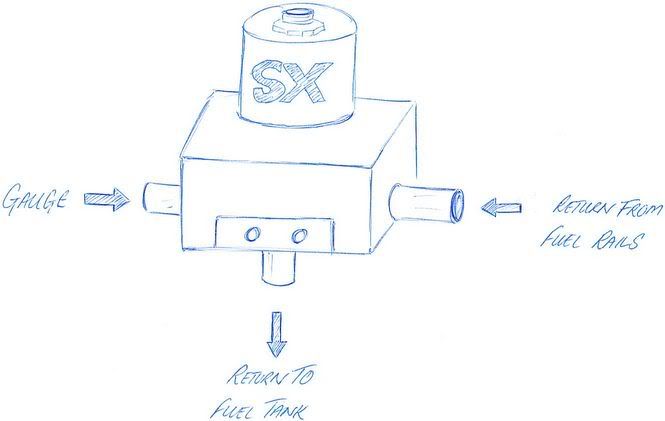
Dyney, I think I've sorted it all. It was realising that the FPR was at the end of the flow diagram that cracked it. Just need to break into the return line/pipe for the 2nd Tee.Interesting that one of the return pipes is smaller than the other.
I'm trying to keep all the Scooby parts stock and not too butchered.
If this string of mods don't cut it on the hill climbs it ALL comes off the car and will get sold off, car and all!
911's are so easy!
Graham.
How strange is that?
Anyway, Jon, pics much appreciated.
Dyney, I think I've sorted it all. It was realising that the FPR was at the end of the flow diagram that cracked it. Just need to break into the return line/pipe for the 2nd Tee.Interesting that one of the return pipes is smaller than the other.
I'm trying to keep all the Scooby parts stock and not too butchered.
If this string of mods don't cut it on the hill climbs it ALL comes off the car and will get sold off, car and all!
911's are so easy!
Graham.
Originally Posted by 911
If this string of mods don't cut it on the hill climbs it ALL comes off the car and will get sold off, car and all!

Thread Starter
Scooby Regular
Joined: May 2004
Posts: 11,341
Likes: 1
Exactly, this is why I need help.
I originally had the flow as:
Tank to pump / pump to filter / filter to inlet of FPR (SX type) / outlet of FPR to '1st Tee' inlet. The Tee would feed each side of the engine injector rails.
The two returns off the exit ends of the rails would be bought together by the 2nd Tee and the then the fuel returned to tank.
But there is a flaw here. A quick look last night at the pipes on the underside of the manifold has a pipe off one rail the same dia as the inlet feed off the filter, but the return off the other rail is much smaller dia, prsumeably to balance any operating pressures(?).
If you think about the 3 tubes that come together opposite the filter, the inlet is 8mm, one return is 8mm and the other about 6mm.
My original question is where to put the Tee's.
I was hoping someone could help me by 'marking' on my pic and re-posting back where the Tee's go.
The first one is clear, there is a 60mm long rubber joiner in the feed line, not so clear is the location for the 2nd Tee, and linking the returns together (why would you need to?)
Simplest of all: Can someone put me out of my misery and send a diagram of what to do!
Graham.


Scooby Regular
Joined: Feb 2002
Posts: 1,403
Likes: 0
From: Behind the 400BHP door :)
Oh ****!! You are right Paul! What a F***wit I am
OK hope this is the correct set-up now
Mine is as follows:
OK hope this is the correct set-up now
Mine is as follows:
Last edited by PICKLE; Jan 4, 2005 at 02:37 PM. Reason: correct labelling of diagram!

Tank to pump/pump to filter/ filter Tee'd to left and right rail/ fule rail return tee'd to FPR/ FPR to tank return.
Your first diagram looks fine. Its best also to make sure pipe lenghts are the same.
Your first diagram looks fine. Its best also to make sure pipe lenghts are the same.

Scooby Regular
Joined: Jul 2000
Posts: 2,209
Likes: 0
From: Lancashire
I've drilled and tapped (1/8bsp) the body of my SX (why didn't I buy an aeromotive ???) to make a specific gauge port.
That way I can plumb the return from each rail directly into the reg without an extra T-piece (and the extra pipe work and joints).
Bats diagram looks right to me.
Andrew...
That way I can plumb the return from each rail directly into the reg without an extra T-piece (and the extra pipe work and joints).
Bats diagram looks right to me.
Andrew...
Last edited by AndrewC; Jan 4, 2005 at 02:48 PM.