When you click on links to various merchants on this site and make a purchase, this can result in this site earning a commission. Affiliate programs and affiliations include, but are not limited to, the eBay Partner Network.
Yes there is a way using the diagnostic connectors under the dash.
Unfortunately I only have the MY97 version (separate control module) as they changed the ABS module for the MY98 ( control module mounted on the ABS hydraulic unit).
However both are fitted with the diagnostic connectors so hopefully the procedure is similar.
For MY98 the diagnostic connectors consist of 2 single pin terminals (B81) and a Black 6 pin connector (B82) with pins 3 and 6 populated and should be located under the dash to the right of the centre console.
If they've not been used they maybe taped up out of the way so not always easy to find.
The MY97 connector is a 2 pin so "terminal pin" references will be different in the procedure.
MY98 Similar location to this, but for a RHD
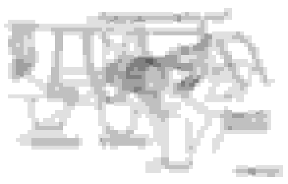
Attached below is the ABS wiring diagram for the MY98.
Here is the diag procedure and fault codes for the MY97.
Last edited by Don Clark; May 24, 2023 at 06:33 PM.
I diagnosed mine this way, It does look daunting, But once you get the flashing lights, video them on your phone, so you can count the flashes easier. Or pop a video on here and someone might be able to read it for you. It can be like looking into The Matrix sometimes, but then eventually it does click.
Unfortunately I only have the LHD version of the bulkead wiring diagram, but as mentioned in post #2 for RHD it will be located on the right hand side of the centre console, in the same area as the check connector and green test connectors (B75) & (B76)
Under the dash are 2x yellow plugs joined/2 x black plugs joined ,2x green plugs hanging and 2 single black plugs which i joined and this made the light go on and off in quick sucession and that was it.
Under the dash in a fairly close grouping you should have the two two pin green connectors (not connected) and two single pin black connectors (not connected) as per image below....
With these connectors (but maybe taped up out of the way) you should have a 6 pin black connector block with wires in position 3 (Yellow/red) and 6 (White/blue) used for ABS testing.
plus two loose ternminated black wires as shown and marked below
The yellow connectors I would assume as being air bag wiring.
The other connected black connectors could be anything else.
Out of interest what is the 10th character of your VIN? V, W or X?
Last edited by Don Clark; Jun 6, 2023 at 12:07 PM.
My 10th character is a w and i connected the two single black connectors in your top diagram the other larger black connectors with 1 wire on one and 2 wires on the other are connected and have been for nearly 25 years,.Thanks.
i connected the two single black connectors in your top diagram
The single pin black connectors should be left unconnected as they are for reading ECU fault codes.
the other larger black connectors with 1 wire on one and 2 wires on the other are connected and have been for nearly 25 years,.Thanks.
If this refers to the black connector plus terminated wires arrowed in red below
Then there's your problem.
If not maybe an image would help clear things up.
However the MY01 seems to use the same black 6 pin connector.
Only pin 6 needs to be connected as per attached pdf below
As said before if the ABS diag terminal pins/connector have not been used before they may be taped up out of the way for you to find. (probable back against the loom
they all emerge from the same bit of loom as below
B125/126 - Black Read connectors
B75/76 - Green Test mode connectors
B81 2 diagnosis terminal wires
B82 - 6 pin diagnosis connector
As i've no idea what the large black connectors are, I cannot say as you've not shared any info / images about them.
I thought you couldn't find the single wires?
You are now on your own.
I apologise if i have upset you and i believe i have described what connectors i have previously but have not sent any images as i do not have the technology to do so.