
Projector retrofit, the simpler way.


OK, got my projectors delivered this week and have spent some time getting the kit fitted, and taking some pics as I went along.
So, to start: remove the grille:
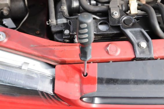
Using a suitable screwdriver, press down on the tang of the clip and pull the grille slightly forward to release the clip. Do this at both sides, then LIFT the grille out of the bottom retainers.
Place to one side in a safe place so as not to fall over it/tread on it
Now, undo the small screws at the top outer edges of the headlights. These hold the top of the sidelight in place:
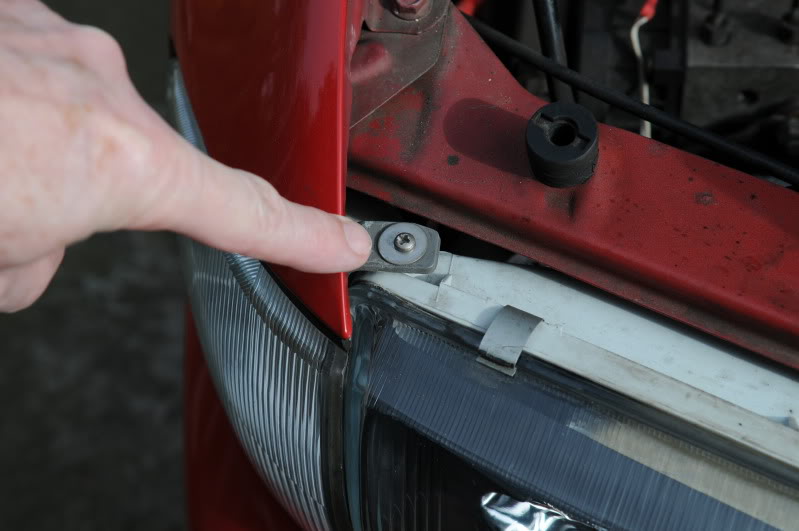
Pull the sidelight forwards. It is held in by a ball and socket arrangement, so pull STRAIGHT forwards. Don't worry too much if you DO snap off one of the ball-bits, I did YEARS ago, and repaired it with something called Miliput Epoxy putty, it's been like that for years with no ill-effect:
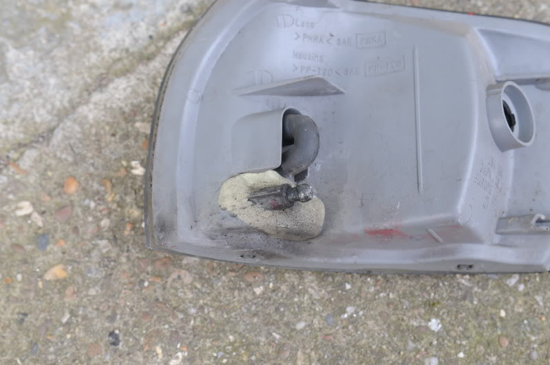
The epoxy putty is the stuff that looks like plasticscene.
Now undo the two bolts that hold the outer edge of the light. These are hidden by the sidelight. The eagle eyed will note that those on mine have been replaced by stainless:
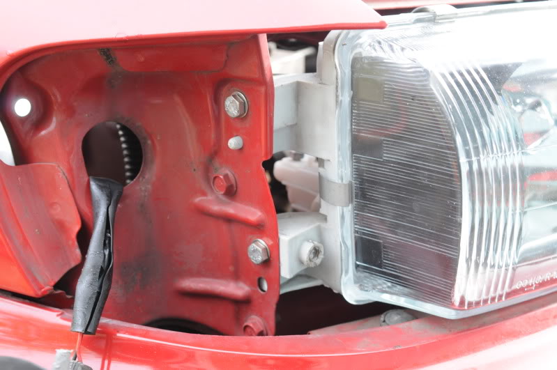
And the two on the inner edge, normally hidden by the grille, more stainless:
That's the lights out, then:
Now for the fun bit. First, prise up the four spring clips that hold each light together, put THOSE in a safe place too Place the lights, one at a time, in the oven, pre-heated to 150 degrees Celsius, for 5 minutes each one.
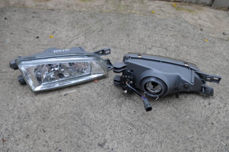
Using oven gloves etc to handle them, place face down on a towel, and use a large flat screwdriver to GENTLY prise up the rear away from the glass. Work carefully, and go around until you can pull the two bits apart.
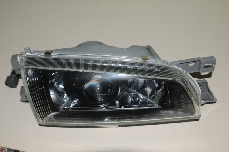
Then, undo the single screw at the inner end and remove and put aside the shroud. Mine was silvered, it got sprayed satin black. This is what the light looks like now:
Now, unscrew the MANUAL height adjuster if yours has them. If they are elctrically adjusted, leave that adjuster in place.
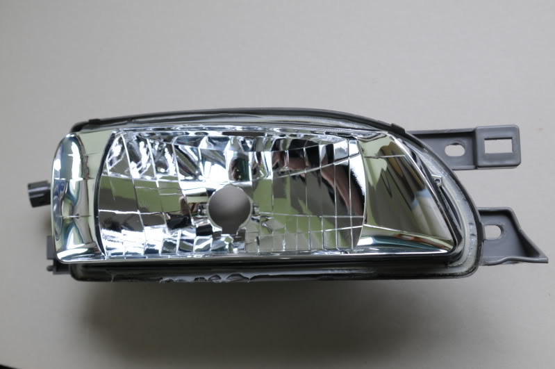
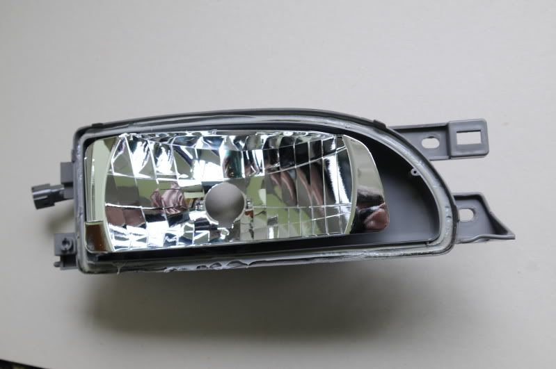
Unscrew the HORIZONTAL, (side to side), adjuster with a 10 mm spanner/socket until the threads are free of it's captive nut. Prise up the ball joint at the other end from INSIDE the light, on electrically adjusted models, prise IT'S ball joint up too, and the reflector will now be free of the back.
DO NOT TOUCH THE INSIDE OF THE REFLECTOR WITH YOUR BARE HANDS AS IT IS VERY HARD TO CLEAN OFF FINGERPRINTS WITHOUT DESTROYING THE SILVERING!
Put the parts of the light aside in a safe place.
Now let's look at what you get in the kit:
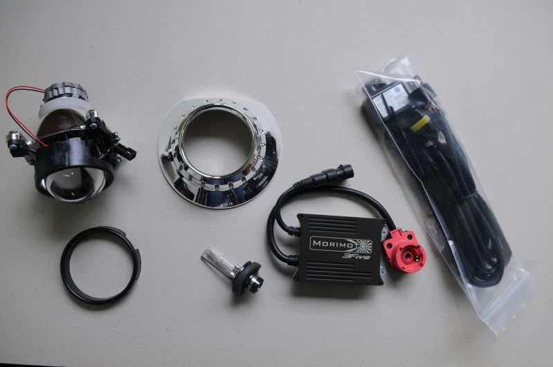
Top left to right: projector, shroud, wiring loom,
Bottom left to right: easy shroud fitting ring, D2S bulb, ballast.
Unscrew the two metal retaining rings from the rear of the projector. DO NOT LOSE the rubber and metal washers that drop out.
Prise off the black rubber collar and the H4 fitting ring, it is metal with 3 spigots sticking out.
These need to be modified to look like the one on the right, the one on the left is as they come:
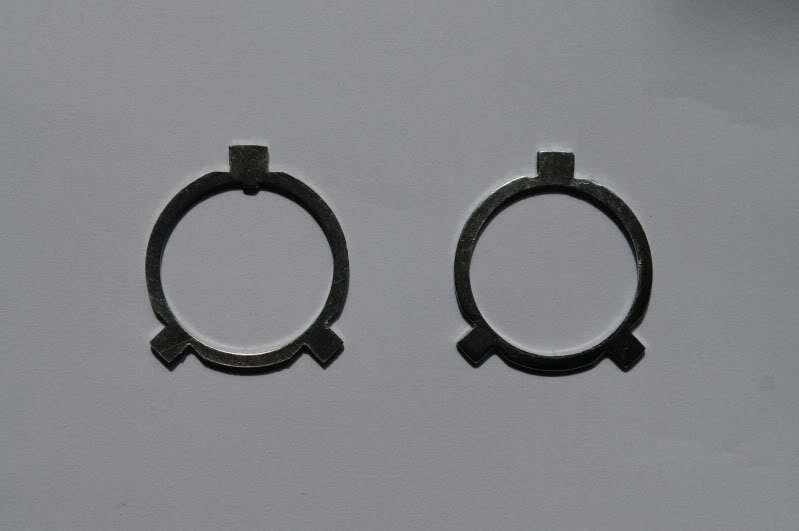
This is because for some reason, the H4 bulb is tilted through about 15 degrees in it's housing on these lights, (one wonders if that is whay they are so CRAP?), and we need the projector to sit level.
Now, offer up the projector, still with it's white plastic crush washer, into the reflector, remembering NOT to touch the reflector surface, (I wore plastic gloves).
Mark the lower reflector surface with a waterproof felt, scriber etc, where the two lower projector bolts touch, remove projector and using a dremel, etc, remove some bits of the lower reflector until the projector will sit vertically. Remove bits at a time, doing most of the dremel work from OUTSIDE the reflector, do not worry, your shrouds will hide the holes. Brush any dust out of the reflector with much blowing and a VERY soft cloth, DO NOT rub hard!
Fit the projector in place, with it's spigot ring on the rear of the reflector, and tighten the FIRST metal ring. Keep checking all is level/vertical.
Once mine was satisfactory, I Araldited the lower bolt protrusions where they came through the reflector, leaving them standing that side down on a plastic bag. Once the Araldite had hardened, I cut the bag back and taped over it with black electrician's tape. You can see that on the next but one pic
Now offer up the new shrouds.
They too will need to be cut, top and bottom, to fit. Remove a bit at a time until you are satisfied, file down any sharp edges, push shroud fitting rings firmly into the rears, and push the whole lot firmly onto the projectors.
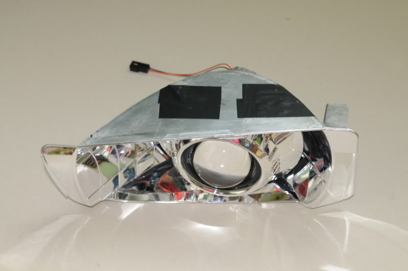
This second pic shows the UNDERSIDE of the relector with the holes sealed with Araldite and tape:
Refit the refectors into the lights, remembering a bit of grease on ball joints/threads.
Replace the shrouds that came out of the light earlier, one screw holds them in place.
The lights can now be put back together. Place glass on top of rear, (after THOROUGHLY cleaning and polishing the INSIDE of the glass).
Back into the oven for five minutes, remove and press down firmly with it face down on a towel, then refit glass clips, (you did remember to put them somewhere safe, didn't you?), and leave to cool.
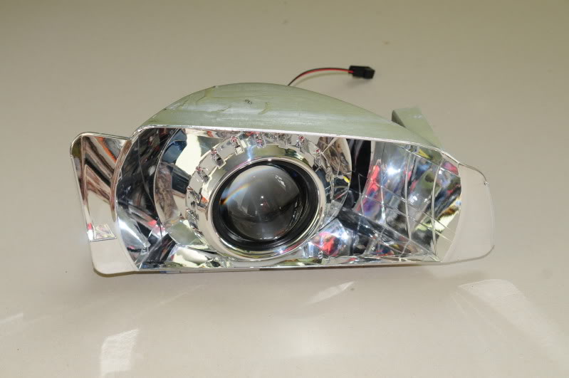
That's one of mine finished. The eagle eyed will again notice that the projector shrouds are now satin black too. This is because, in attempting to fit the "BIXENON" stckers that came with the kit to the outer edge of the shroud, the clear tape holding MINE fetched the silvering off the shroud and the letters didn't stick anyway, so I took them off and sprayed the lot black. If I don't like it, I'll take the lights apart later and get some more shrouds
At this point, fit the bulbs, the two bits that fell out earlier when you unscrewed the two metal rings, are used to help hold them in place. The rubber one goes against the bulb base, the metal spring goes on top of it and the SECOND metal ring you unscrewed earlier holds the whole lot together.
I then made a small slot in the lower edge of the rear of the lamp housing on the plastic part of the headlight, in order to accomodate the thin wires to the dipping mechanism. they should be led out of the rear of the light.
I slightly modified the rubber seals from the rear of the lights:
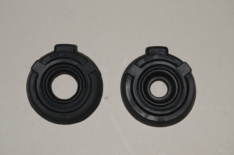
On the left: modified, on the right: as it came. I used a sharp craft knife, (actually a scalpel), to slice off the thick part of the rubber centre, the bit that normally fits over an H4 bulb base.
Ok, the wiring:
Here is a pic of the wiring loom: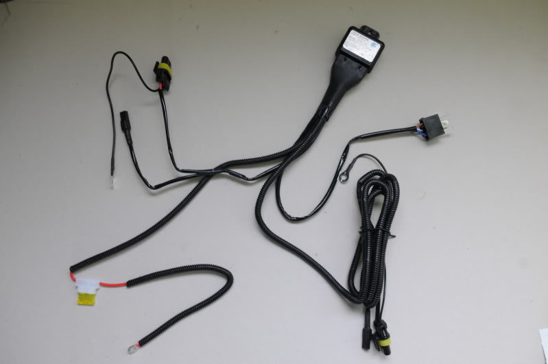
Fairly standard: Working clockwise from the larger box at the top centre with it's silver label, this is the relay.
Then we have: H4 connector, (plugs into your old bulb connector), long sub-wiring loom to offside light, positive lead with 20A fuse in holder, shorter sub-wiring loom to nearside light.
Each of the two sub-looms mentioned has three parts: a larger connector to go to the ballast, a smaller connector to go to the dipping mechanism within the projector, and an earth from the ballast connector with a ring terminal on the end. Don't worry, the push-fit connectors are made so you can't connect them wrong
I cut off the fuse and holder, and soldered on a spade connector and cover to go to my little fusebox for auxilliary stuff.
I then wired up and away it went. I left the lights just sitting in place while I tested everything, then, when I was satisfied, removed them and taped everything against water ingress if necessary, (like the H4 connector), and zip-tied wires out of the way, (you get three zip-ties with the kit).
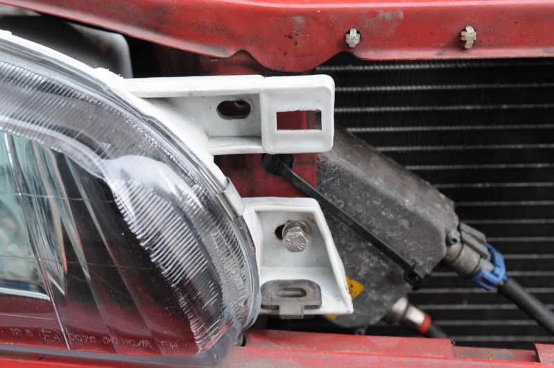
Here's what one looks like fitted:
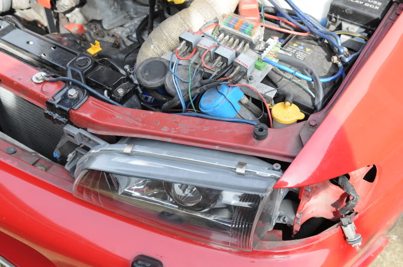
You can just see the positive wire going to the second nearest fuse from the camera.
Note also the white sealant all the way round the light. This is a non-setting mastic called Carafax, and I smeared it into the joint between glass and rear so as to be SURE it was waterproof. I didn't want any nasty surprises caused by poor sealing after they had been split.
Tonight, when it gets dark, I'll take the car out and set them for level. I'll also try and get some pics of the cutoff, which, in daylight, LOOKS spot-on.
Was it simple? Not really, but it wasn't beyond the wit of any competent DIY-er. It took me around 6 hours of ACTUAL work, not counting time for paint to go off, glue to set, etc.
Thoughts so far:
1. The wiring WAS plug and play! This is completely different from the kit I fitted for a mate, bought off a VERY well known trader, where we had to muck about removing connectors out of the H4 plug and doing trial and error until we got it right. This kit works out of the box!
2. Looking at the projectors, I can see that it would be DEAD EASY to undo the four self tappers holding them together, and change the dip from RHD to LHD. One screw inside and a bit of fiddling with spring wires, but definitley do-able. It WOULD mean taking the whole thing apart again, so I don't envisage doing it, but was thinking of that kit Joey turbo bought, and his was at an angle too.
If you're reading this, Joey, give it a go, and modify the spigot rings so your projectors sit level.
Hopefully cutoff pics later.
Alcazar
So, to start: remove the grille:
Using a suitable screwdriver, press down on the tang of the clip and pull the grille slightly forward to release the clip. Do this at both sides, then LIFT the grille out of the bottom retainers.
Place to one side in a safe place so as not to fall over it/tread on it
Now, undo the small screws at the top outer edges of the headlights. These hold the top of the sidelight in place:
Pull the sidelight forwards. It is held in by a ball and socket arrangement, so pull STRAIGHT forwards. Don't worry too much if you DO snap off one of the ball-bits, I did YEARS ago, and repaired it with something called Miliput Epoxy putty, it's been like that for years with no ill-effect:
The epoxy putty is the stuff that looks like plasticscene.
Now undo the two bolts that hold the outer edge of the light. These are hidden by the sidelight. The eagle eyed will note that those on mine have been replaced by stainless:
And the two on the inner edge, normally hidden by the grille, more stainless:
That's the lights out, then:
Now for the fun bit. First, prise up the four spring clips that hold each light together, put THOSE in a safe place too
Place the lights, one at a time, in the oven, pre-heated to 150 degrees Celsius, for 5 minutes each one.Using oven gloves etc to handle them, place face down on a towel, and use a large flat screwdriver to GENTLY prise up the rear away from the glass. Work carefully, and go around until you can pull the two bits apart.
Then, undo the single screw at the inner end and remove and put aside the shroud. Mine was silvered, it got sprayed satin black. This is what the light looks like now:
Now, unscrew the MANUAL height adjuster if yours has them. If they are elctrically adjusted, leave that adjuster in place.
Unscrew the HORIZONTAL, (side to side), adjuster with a 10 mm spanner/socket until the threads are free of it's captive nut. Prise up the ball joint at the other end from INSIDE the light, on electrically adjusted models, prise IT'S ball joint up too, and the reflector will now be free of the back.
DO NOT TOUCH THE INSIDE OF THE REFLECTOR WITH YOUR BARE HANDS AS IT IS VERY HARD TO CLEAN OFF FINGERPRINTS WITHOUT DESTROYING THE SILVERING!
Put the parts of the light aside in a safe place.
Now let's look at what you get in the kit:
Top left to right: projector, shroud, wiring loom,
Bottom left to right: easy shroud fitting ring, D2S bulb, ballast.
Unscrew the two metal retaining rings from the rear of the projector. DO NOT LOSE the rubber and metal washers that drop out.
Prise off the black rubber collar and the H4 fitting ring, it is metal with 3 spigots sticking out.
These need to be modified to look like the one on the right, the one on the left is as they come:
This is because for some reason, the H4 bulb is tilted through about 15 degrees in it's housing on these lights, (one wonders if that is whay they are so CRAP?), and we need the projector to sit level.
Now, offer up the projector, still with it's white plastic crush washer, into the reflector, remembering NOT to touch the reflector surface, (I wore plastic gloves).
Mark the lower reflector surface with a waterproof felt, scriber etc, where the two lower projector bolts touch, remove projector and using a dremel, etc, remove some bits of the lower reflector until the projector will sit vertically. Remove bits at a time, doing most of the dremel work from OUTSIDE the reflector, do not worry, your shrouds will hide the holes. Brush any dust out of the reflector with much blowing and a VERY soft cloth, DO NOT rub hard!
Fit the projector in place, with it's spigot ring on the rear of the reflector, and tighten the FIRST metal ring. Keep checking all is level/vertical.
Once mine was satisfactory, I Araldited the lower bolt protrusions where they came through the reflector, leaving them standing that side down on a plastic bag. Once the Araldite had hardened, I cut the bag back and taped over it with black electrician's tape. You can see that on the next but one pic
Now offer up the new shrouds.
They too will need to be cut, top and bottom, to fit. Remove a bit at a time until you are satisfied, file down any sharp edges, push shroud fitting rings firmly into the rears, and push the whole lot firmly onto the projectors.
This second pic shows the UNDERSIDE of the relector with the holes sealed with Araldite and tape:
Refit the refectors into the lights, remembering a bit of grease on ball joints/threads.
Replace the shrouds that came out of the light earlier, one screw holds them in place.
The lights can now be put back together. Place glass on top of rear, (after THOROUGHLY cleaning and polishing the INSIDE of the glass
).Back into the oven for five minutes, remove and press down firmly with it face down on a towel, then refit glass clips, (you did remember to put them somewhere safe, didn't you?), and leave to cool.
That's one of mine finished. The eagle eyed will again notice that the projector shrouds are now satin black too. This is because, in attempting to fit the "BIXENON" stckers that came with the kit to the outer edge of the shroud, the clear tape holding MINE fetched the silvering off the shroud
and the letters didn't stick anyway, so I took them off and sprayed the lot black. If I don't like it, I'll take the lights apart later and get some more shroudsAt this point, fit the bulbs, the two bits that fell out earlier when you unscrewed the two metal rings, are used to help hold them in place. The rubber one goes against the bulb base, the metal spring goes on top of it and the SECOND metal ring you unscrewed earlier holds the whole lot together.
I then made a small slot in the lower edge of the rear of the lamp housing on the plastic part of the headlight, in order to accomodate the thin wires to the dipping mechanism. they should be led out of the rear of the light.
I slightly modified the rubber seals from the rear of the lights:
On the left: modified, on the right: as it came. I used a sharp craft knife, (actually a scalpel), to slice off the thick part of the rubber centre, the bit that normally fits over an H4 bulb base.
Ok, the wiring:
Here is a pic of the wiring loom:
Fairly standard: Working clockwise from the larger box at the top centre with it's silver label, this is the relay.
Then we have: H4 connector, (plugs into your old bulb connector), long sub-wiring loom to offside light, positive lead with 20A fuse in holder, shorter sub-wiring loom to nearside light.
Each of the two sub-looms mentioned has three parts: a larger connector to go to the ballast, a smaller connector to go to the dipping mechanism within the projector, and an earth from the ballast connector with a ring terminal on the end. Don't worry, the push-fit connectors are made so you can't connect them wrong
I cut off the fuse and holder, and soldered on a spade connector and cover to go to my little fusebox for auxilliary stuff.
I then wired up and away it went. I left the lights just sitting in place while I tested everything, then, when I was satisfied, removed them and taped everything against water ingress if necessary, (like the H4 connector), and zip-tied wires out of the way, (you get three zip-ties with the kit).
Here's what one looks like fitted:
You can just see the positive wire going to the second nearest fuse from the camera.
Note also the white sealant all the way round the light. This is a non-setting mastic called Carafax, and I smeared it into the joint between glass and rear so as to be SURE it was waterproof. I didn't want any nasty surprises caused by poor sealing after they had been split.
Tonight, when it gets dark, I'll take the car out and set them for level. I'll also try and get some pics of the cutoff, which, in daylight, LOOKS spot-on.
Was it simple? Not really, but it wasn't beyond the wit of any competent DIY-er. It took me around 6 hours of ACTUAL work, not counting time for paint to go off, glue to set, etc.
Thoughts so far:
1. The wiring WAS plug and play!
This is completely different from the kit I fitted for a mate, bought off a VERY well known trader, where we had to muck about removing connectors out of the H4 plug and doing trial and error until we got it right. This kit works out of the box!2. Looking at the projectors, I can see that it would be DEAD EASY to undo the four self tappers holding them together, and change the dip from RHD to LHD. One screw inside and a bit of fiddling with spring wires, but definitley do-able. It WOULD mean taking the whole thing apart again, so I don't envisage doing it, but was thinking of that kit Joey turbo bought, and his was at an angle too.
If you're reading this, Joey, give it a go, and modify the spigot rings so your projectors sit level.
Hopefully cutoff pics later.
Alcazar
Last edited by alcazar; Apr 7, 2011 at 10:24 AM.
Here's the first, showing dip beam with VERY sharp cutoff:
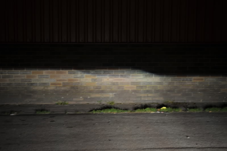
The car is standing on level ground, around 30 feet from the wall. I shall be having the HEIGHT checked when it goes for MoT on 9th May, I expect no probs with the pattern
Now the next shot, main beams;
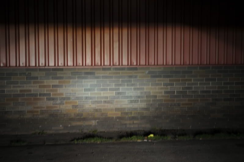
Good light, excellent focus, good spread.
These are highly recommended.
Someone on the thread started by Joey turbo was going to do a group buy. I paid �220 for these, delivered, so anything LESS than that is a bargain!
http://www.theretrofitsource.com/
http://www.theretrofitsource.com/ind...u8m163krjegaeo
And mine are these: http://www.theretrofitsource.com/pro...roducts_id=237
The car is standing on level ground, around 30 feet from the wall. I shall be having the HEIGHT checked when it goes for MoT on 9th May, I expect no probs with the pattern
Now the next shot, main beams;
Good light, excellent focus, good spread.
These are highly recommended.
Someone on the thread started by Joey turbo was going to do a group buy. I paid �220 for these, delivered, so anything LESS than that is a bargain!
http://www.theretrofitsource.com/
http://www.theretrofitsource.com/ind...u8m163krjegaeo
And mine are these: http://www.theretrofitsource.com/pro...roducts_id=237
Last edited by alcazar; Apr 7, 2011 at 10:16 AM.
I've just remembered, once the HID kit was in place, the driving lights refused to work.
They are relayed, with the trigger off the main beam wiring. I traced the problem to the new electronic relay: it no longer draws sufficient current to trigger the driving light relay
I eventually solved it by triggering the driving light relay off the unused headlight connector behind the o/s headlight.
This has three terminals, seen from the FRONT, (the side that goes onto the H4 bulb), they look like this:
__
| |
Take a wire from the LEFT hand vertical connector to relay 85, and another from the RIGHT hand vertical connector to relay 86, this relay no longer needs an earth.
That's it: your driving lights will now work as normal.


Thanks for the advice Jeff, will give it a go re-levelling once I'vecgut off the locating lug.
Also, I noticed my driving lights didn't work, but assumed I'd pulled a connector out, and couldn't be bothered to look for it in the dark. I'd have never worked that one out.
Glad to see one of the main headlight critics with some decent lights.
BTW, did you get hit with a customs charge?
Also, I noticed my driving lights didn't work, but assumed I'd pulled a connector out, and couldn't be bothered to look for it in the dark. I'd have never worked that one out.
Glad to see one of the main headlight critics with some decent lights.
BTW, did you get hit with a customs charge?
No, no customs charge, they say they don't get it. It's on their site.
If you are just levelling the projectors, you can do it without splitting the lights agin.
However, if you DO have to change the dips, you'll have to bite the bullet and open them up again.
If you are just levelling the projectors, you can do it without splitting the lights agin.
However, if you DO have to change the dips, you'll have to bite the bullet and open them up again.
Trending Topics
I'd have to split the projectors then. Because if I did level them up, the LHD cut-off would be more visible, and cause some issues. I've a feeling that mine don't come apart so easily. Your ones look a lot better built.

Thanks Harvey, hope to be able to show you the fit on 9th May.


Shouldn't be a proble. go to www.theretrofitsource.com ad have a look at what's available. If you already HAVE a set of preojectors, they can maybe tell you want will, and what won't fit. The dips could be made into projectors also.
Matt at the Retrofit Source is a great bloke, really wants to help and NOT just to sell you stuff.
Drop him an e-mail with what you THINK might work and he will comment, almost by return.
Matt at the Retrofit Source is a great bloke, really wants to help and NOT just to sell you stuff.
Drop him an e-mail with what you THINK might work and he will comment, almost by return.

Not at the mo, but can do, they do lolok OEM until you look at the lights, the shrouds being black add stealth.
I'll try and get one today. Not working until 3.30 so should have time.
I'll try and get one today. Not working until 3.30 so should have time.

 g[/IMG]
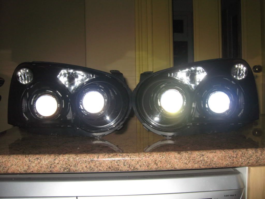
just had to change the outer plastic lenses on my blobeye projector retrofit. they had yellowed & showed signs of cracking/laminating. any ideas what could have caused this, heat from the hids? will post some pics later.
How long had they been in place and where were they from, or what make were they?
The Retrofit Source have interesting info on cheap vs decent bulbs, ballasts, projectors etc.
The Retrofit Source have interesting info on cheap vs decent bulbs, ballasts, projectors etc.

Thread
Thread Starter
Forum
Replies
Last Post