

Gauge fitting - MY00 UK turbo

Thread Starter
Scooby Regular
Joined: May 2012
Posts: 259
Likes: 0
From: Greenhithe, Kent
Right, so there are a couple of other threads on here about fitting gauges, but I'd like to do my own for a couple of reasons. Firstly, I've not seen anyone post up comprehensively about fitting gauges to a MY00 UK turbo, and secondly, it'd be good to get some feedback as I go, and hopefully other people can extract some information from this.
The idea is simply to fit oil temperature, oil pressure and boost gauges in a triple pod which will replace the centre cubby on the dash. I'll post pictures and ask questions as I go along, and hopefully people will intervene with answers for any questions I have, so I'm learning as I go along too. It is a work in progress, and I'll update as I go along.
Scoobyc and Funkmasterjay have posted threads up about fitting these gauges - despite being comprehensive, the one from Scoobyc is for a V4 STi '98 Impreza, and although it's the same engine as mine, Jay's wasn't really a guide as such, as it was part of his Project Recession.
I had attempted to follow the thread from Scoobyc, and although the basic principles are the same, the layouts are different so I couldn't really bludgeon in and get on with it. The gauges I have are the LCD EVO range by Prosport (bought from R-Spec), and a pressure/temperature gauge fitting kit from Scoobyparts.
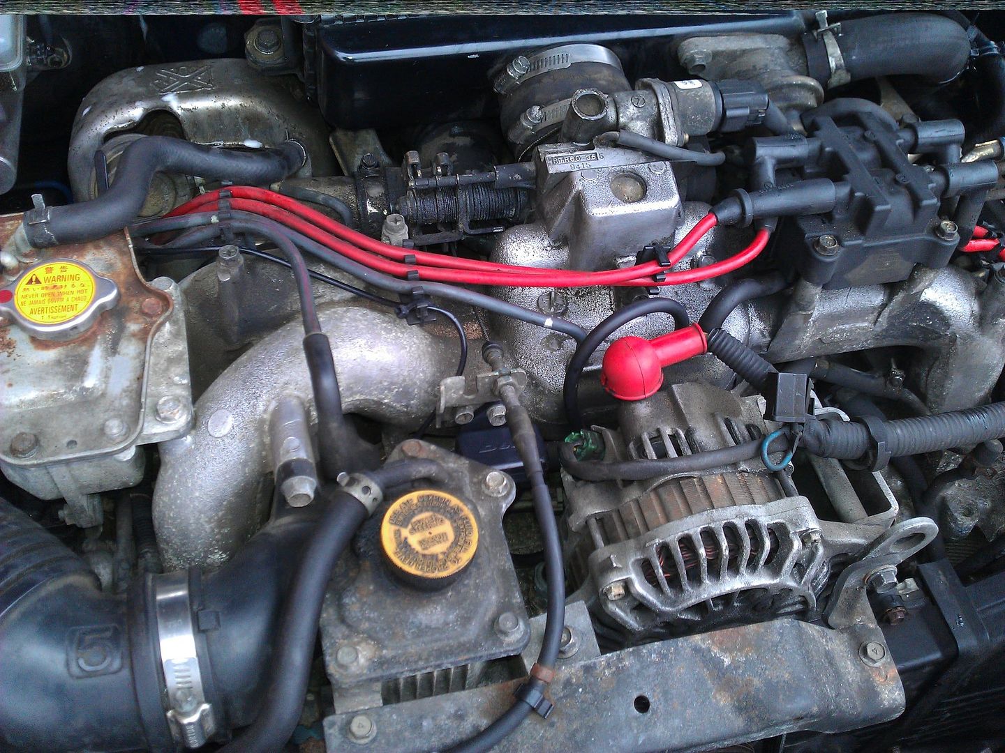
Anyway, picture I is the engine bay, as it is today, no prep for these gauges done so far. It's certainly different from Scoobyc's v4 - so, I presume it's a v5? If that is incorrect, do let me know.
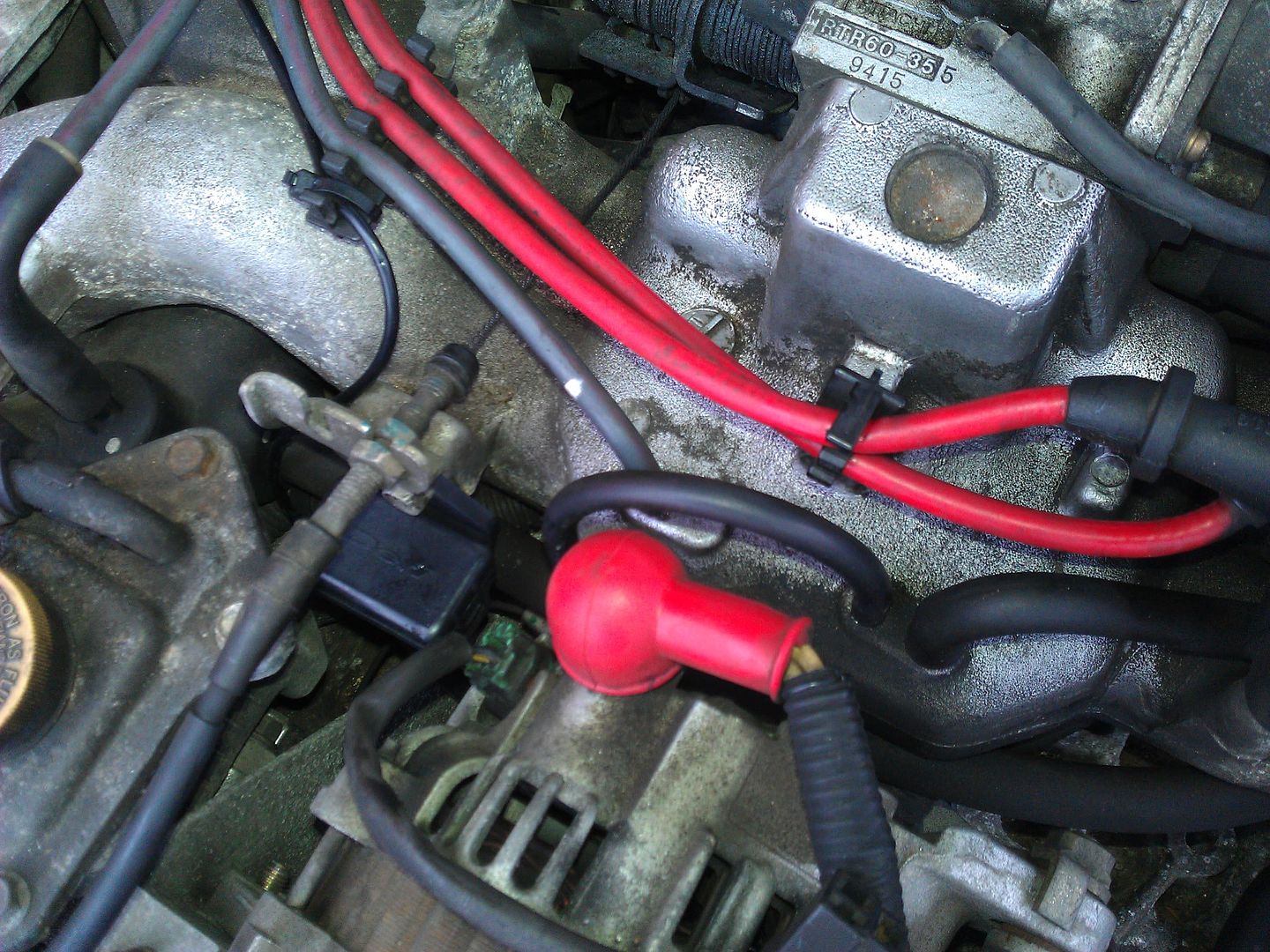
Picture II shows the intended location of the T-piece for the boost gauge (as recommended in the Scoobyc thread) - will cut here and plumb in.
Picture III is where the oil pressure gauge will be plumbed in, with the aid of the fitting kit. It is underneath and slightly behind the alternator, which will have to be removed in order to access this cleanly.
The idea is simply to fit oil temperature, oil pressure and boost gauges in a triple pod which will replace the centre cubby on the dash. I'll post pictures and ask questions as I go along, and hopefully people will intervene with answers for any questions I have, so I'm learning as I go along too. It is a work in progress, and I'll update as I go along.
Scoobyc and Funkmasterjay have posted threads up about fitting these gauges - despite being comprehensive, the one from Scoobyc is for a V4 STi '98 Impreza, and although it's the same engine as mine, Jay's wasn't really a guide as such, as it was part of his Project Recession.
I had attempted to follow the thread from Scoobyc, and although the basic principles are the same, the layouts are different so I couldn't really bludgeon in and get on with it. The gauges I have are the LCD EVO range by Prosport (bought from R-Spec), and a pressure/temperature gauge fitting kit from Scoobyparts.
Anyway, picture I is the engine bay, as it is today, no prep for these gauges done so far. It's certainly different from Scoobyc's v4 - so, I presume it's a v5? If that is incorrect, do let me know.
Picture II shows the intended location of the T-piece for the boost gauge (as recommended in the Scoobyc thread) - will cut here and plumb in.
Picture III is where the oil pressure gauge will be plumbed in, with the aid of the fitting kit. It is underneath and slightly behind the alternator, which will have to be removed in order to access this cleanly.
Last edited by ace1981; Mar 9, 2013 at 03:11 PM. Reason: Gauge details
Thread Starter
Scooby Regular
Joined: May 2012
Posts: 259
Likes: 0
From: Greenhithe, Kent
I am looking for a cutaway or suitable hole in the bulkhead somewhere in the area shown in picture IV, but there doesn't seem to be any instantly accessible.
Scoobyc went for one behind the brake pipes (close up in picture V), but at the moment I'm not sure how accessible these would be from inside the car. Picture VI is a shot of the underside of the dash, looking up from the driver's footwell.
Is it easy to route the pipes into the cabin on this side of the car and be able to feed them up through the dash to the centre cubby? It's a killer for your back to have a look up from the footwell, and it is a mass of tangled wires.
Ultimately I need to plan this ahead as I will wire in the gauges for day/night illumination (white when lights are off, green when lights are on).

Scooby Newbie
Joined: Oct 2012
Posts: 13
Likes: 0
From: norfolk
On my00 I used the blanked off vac pipe for my boost gauge witch is just next to the vac pipe for rec valve witch in ur second pic of first post just behind alternator wire u can just see a little stump that saves cutting in to pipes and mine works fine there.
Thread Starter
Scooby Regular
Joined: May 2012
Posts: 259
Likes: 0
From: Greenhithe, Kent
Do you mean the blue arrow?

Thread Starter
Scooby Regular
Joined: May 2012
Posts: 259
Likes: 0
From: Greenhithe, Kent
I had wondered what that was - so I presume by using this, I don't need the t-piece as the pipe runs directly from here to the boost gauge sender (which I will mount on an unused bracket just in front of the strut brace on the left hand side of picture I). That does seem a tidier option.
Anyone else use this method? Is it any less accurate than cutting the pipe I'd originally planned to use?
Anyone else use this method? Is it any less accurate than cutting the pipe I'd originally planned to use?
Trending Topics

Thread Starter
Scooby Regular
Joined: May 2012
Posts: 259
Likes: 0
From: Greenhithe, Kent
I want to round up as much information as I can on it, so I can get it right first time.
Plumbing in the gauges isn't so much of a problem for me; it's the electrical hook-up that are going to cause me headaches as I'm no sparky. Will worry about that at a later date though.
Thread Starter
Scooby Regular
Joined: May 2012
Posts: 259
Likes: 0
From: Greenhithe, Kent
OK, so far the plan will be this. Anyone see any issues so far?
As the intercooler has to come off to get to cylinder 3 and therefore the ideal spot for the oil temperature gauge, I've not marked it up yet. That'll be the last one I do.
As the intercooler has to come off to get to cylinder 3 and therefore the ideal spot for the oil temperature gauge, I've not marked it up yet. That'll be the last one I do.


Looks the same as when I did mine, except that all my wiring etc went through the grommet on the n/s, which is used for aircon on cars so fitted.
What gauges and how many wires to each?
What gauges and how many wires to each?
Thread Starter
Scooby Regular
Joined: May 2012
Posts: 259
Likes: 0
From: Greenhithe, Kent
Gauges to be fitted are Prosports - boost, oil temperature and oil pressure. The instructions are very sketchy, part of the reason for this thread, but each loom has five wires, which are (according to the boost gauge instructions):-
Red - 12v accessory power (positive)
Black - ground negative
White - engine accessory power
Orange - headlight switch (12v switch power)
Green - boost sensor
Firstly I need to work out how best to route the wiring through the bulkhead into the cabin, and then go from there. I'm quite sure I can't daisy-chain these gauges either.

Gauges to be fitted are Prosports - boost, oil temperature and oil pressure. The instructions are very sketchy, part of the reason for this thread, but each loom has five wires, which are (according to the boost gauge instructions):-
Red - 12v accessory power (positive)
Black - ground negative
White - engine accessory power
Orange - headlight switch (12v switch power)
Green - boost sensor
Red - 12v accessory power (positive)
Black - ground negative
White - engine accessory power
Orange - headlight switch (12v switch power)
Green - boost sensor

If they are like Defis, and I reckon they are, you need a permanent live, (on all the time), a switched live, (on with ign only) a lighting live, (on when lights are) and a DECENT earth. Mines runs back to an earthing bar I've fitted near the battery -ve.
I'm unsure about Prosport, the only thing I DO know is that the little plugs at the rear of the gauges can cause trouble unless securely pushed into the gauge socket. Like Defis, they are best taped over when pulling wires through the grommet and under the dash, or you risk pulling the wires out of the little plastic connectors...ask me how I know

Thread Starter
Scooby Regular
Joined: May 2012
Posts: 259
Likes: 0
From: Greenhithe, Kent
Well they won't ALL have the boost sensor wire, will they?
If they are like Defis, and I reckon they are, you need a permanent live, (on all the time), a switched live, (on with ign only) a lighting live, (on when lights are) and a DECENT earth. Mines runs back to an earthing bar I've fitted near the battery -ve.
If they are like Defis, and I reckon they are, you need a permanent live, (on all the time), a switched live, (on with ign only) a lighting live, (on when lights are) and a DECENT earth. Mines runs back to an earthing bar I've fitted near the battery -ve.
Go in via that n/s grommet, it's quite low down, but still much easier than the o/s.
I'm unsure about Prosport, the only thing I DO know is that the little plugs at the rear of the gauges can cause trouble unless securely pushed into the gauge socket. Like Defis, they are best taped over when pulling wires through the grommet and under the dash, or you risk pulling the wires out of the little plastic connectors...ask me how I know
I'm unsure about Prosport, the only thing I DO know is that the little plugs at the rear of the gauges can cause trouble unless securely pushed into the gauge socket. Like Defis, they are best taped over when pulling wires through the grommet and under the dash, or you risk pulling the wires out of the little plastic connectors...ask me how I know
1. yes.
2. Ask on here, it's not difficult. Once the tray is out, you can get at what wires you need easily.
3. If using the coathanger, place the wires and plugs staggered along the length of about 50mm of coathanger and wrap insulation tape round them to cover, in a spiral.
Pull through, remove tape, Robert is your mother's brother.

only the prosports with peak function require a permanent live, i had theses and recently changed to the prosport evo digital ones, these only require the ignition live, if you connect them to permanent live the gauges wont turn off.
Thread Starter
Scooby Regular
Joined: May 2012
Posts: 259
Likes: 0
From: Greenhithe, Kent
1. yes.
2. Ask on here, it's not difficult. Once the tray is out, you can get at what wires you need easily.
3. If using the coathanger, place the wires and plugs staggered along the length of about 50mm of coathanger and wrap insulation tape round them to cover, in a spiral.
Pull through, remove tape, Robert is your mother's brother.
2. Ask on here, it's not difficult. Once the tray is out, you can get at what wires you need easily.
3. If using the coathanger, place the wires and plugs staggered along the length of about 50mm of coathanger and wrap insulation tape round them to cover, in a spiral.
Pull through, remove tape, Robert is your mother's brother.
2. I will be doing exactly that - with the aid of photos as I'm a total pleb when it comes to electrics, connections and wiring
3. That's a good idea. And my mother's brother is actually called Robert. Imagine that.
Thread Starter
Scooby Regular
Joined: May 2012
Posts: 259
Likes: 0
From: Greenhithe, Kent
I'm pretty sure these gauges can't be daisy chained; so I've no idea whether its better to splice three times, employ choc blocks, etc.
Thread Starter
Scooby Regular
Joined: May 2012
Posts: 259
Likes: 0
From: Greenhithe, Kent
Finally got some more time to carry this on from last weekend.
So, this morning I was able to remove the centre cubby, lid and surround. Removing two screws in the back of the cubby will allow you to remove the lid, a further two screws in the sides of the compartment (covered with small rectangular covers) and the cubby and vents are free.
The surround is merely clipped in - one on either side of the heater controls, and two along the bottom. Lever the top clips out with a screwdriver, and then pull the surround up and out from the bottom, and picture VII is the result.
I was lucky with the stereo merely being slotted in and not screwed in, so I disconnected the loom and aerial and put the head unit to one side so it wasn't in the way. Without the stereo, picture VIII is the result.
Following Alcazar's advice, it does seem a much easier and cleaner option to route through a nearside grommet and to the centre console via the area under the glovebox so that is the plan for now, although I will probably need to find another place for the boost gauge sensor, which was originally planned to go on the unused bracket located on top of the offside suspension mount.
Silly question - is the rubber object (near the top of the picture, pear shaped with a small hole in the fatter end) in picture IX completely and safely removable? It sits in the bulkhead behind, below and slightly to the right of the SSQV3, and in a hole slightly smaller than the visible rubber, as I can get my fingers under the outer lip.
I thought this might have been the grommet Alcazar used for his installation, but I was expecting it to be a bit lower than this.
Last edited by ace1981; Mar 16, 2013 at 03:01 PM. Reason: Grommet description
Yes, that's the grommet. No real need to remove it, just cut a cross across it.
My boost gauge sensor is fixed to a piece of alloy about 1mm thick and then to the n/s strut. The thinness of the ally makes the bracket bendable.
My boost gauge sensor is fixed to a piece of alloy about 1mm thick and then to the n/s strut. The thinness of the ally makes the bracket bendable.
Thread Starter
Scooby Regular
Joined: May 2012
Posts: 259
Likes: 0
From: Greenhithe, Kent
Another day, another update.
Thanks to the miserable weather starting to install the senders wasn't really an option today, so instead I chose to refit the pod and route the wires through to the area behind the stereo, in readiness for connecting up (picture X). I also drilled a hole through the floor of the centre cubby trim so the wires from the gauges can all be passed to where they need to be.
I had inserted the gauges into the pods (using the supplied U-shaped brackets prevents them rotating in the slots). I also connected the wiring looms into the respective gauges and labelled them accordingly. Then carefully pushed the wires through the hole in the cubby floor and pulled almost all the slack through.
Put the ends of the wires into a sealed plastic bag - firstly to protect the ends of the threads, secondly as it's easier to pull all the wires down through the dash in one go than separately.
I pushed the bag down past the vents on the left hand side (as you look at them from the cabin) and fed the wires through until I could see the bag through the stereo slot (picture XI), then pulled the bag down gently so that the wires are accessible for connection.
I noticed after replacing the cubby floor / vents with the pod on top that it doesn't sit flush - there's about a quarter inch gap (picture XII). For the time being I haven't screwed it all together so I can look at it when time permits.
Last edited by ace1981; Mar 18, 2013 at 01:50 PM. Reason: Poor grammar
Thread Starter
Scooby Regular
Joined: May 2012
Posts: 259
Likes: 0
From: Greenhithe, Kent
The metal hook on the underside of the pod is obviously hitting something, preventing the pod from sitting flush on the trim for the vents.
I've had a look at the frankly ropey instructions (picture XIII) and it mentions that the metal bracket, presumably from the original cubby lid in picture XIV, needs to be refitted. Not completely sure why, but I imagine this will resolve the problem. By now I was cold and in need of a cup of tea so I bravely gave up and headed back indoors.
I also realised today that the supplied wires for the gauges are nowhere near long enough to run from the gauges down the back of the dashboard and through the bulkhead to the respective senders, so a quick dash to an electrical goods store was in order - two metres of cheap multicore wire should do the trick.
Anyone foresee any problems with the multicore being slightly thicker than the wires supplied with the gauge (picture XV)? If it's a stupid question, bear in mind I'm no sparky and my electrical know-how does not extend beyond changing a lightbulb.
Thread Starter
Scooby Regular
Joined: May 2012
Posts: 259
Likes: 0
From: Greenhithe, Kent
Another minor update.
I have today and tomorrow off work, and fortunately the weather hasn't been as bad as recent weeks, so I decided to man up and get back onto this. It is still cold out, so I expect I'll be updating this thread every few hours when I come back in for a cup of tea and a defrost.
So far I've managed to remove the grommet in the firewall and cut through the hole to feed the wires through when they are being married up to the gauges / senders (pictures XVI and XVII)
It was a bit tricky to do in situ so I ended up taking it out, which also gave me the opportunity to see where exactly the opening is from the footwell. Answer - a lot higher up than I expected, but by no means out of reach (pictures XVIII and XIX).
Thread Starter
Scooby Regular
Joined: May 2012
Posts: 259
Likes: 0
From: Greenhithe, Kent
One other thing I've noticed is the appalling fit of the gauge pod. I've followed the fitting instructions, refitted the metal bracket from the original cubby lid; but doing this causes the rear of the pod to sit higher than the surrounding dash, and the front to sit too high and too far forward.
The hook protruding from the front of the pod is obviously what's causing it; but as it's moulded in, the only way to remove it is to cut part or all of it off.
Have I missed something, or is this just a design flaw?
The hook protruding from the front of the pod is obviously what's causing it; but as it's moulded in, the only way to remove it is to cut part or all of it off.
Have I missed something, or is this just a design flaw?
Thread Starter
Scooby Regular
Joined: May 2012
Posts: 259
Likes: 0
From: Greenhithe, Kent
Right, after much deliberation today I have decided that I've approached these gauges in completely the wrong way - putting them in first and then attempting the wiring, etc made things much more difficult than they needed to be. Well, when I say much deliberation, I mean an hour and a half spent fiddling with choc blocks and wire cutters, etc, which resulted in merely the earth connections being done (and then constantly working their way out of the choc block).
The fact the pod and gauges were already in on top of the vents (and effectively in the way) meant that routing the wires and connecting them up was too difficult in a confined space. Add that to a lack of patience and a short temper and it's potentially disastrous.
As I'm fed up of the sight of gauges and wires at the moment, I'll come back to this in a week or two - in the meantime, I'll rip them all out, carefully of course, and start again from scratch. Wiring first, testing with gauges loose in the cabin and NOT in the pod second, under the bonnet third, tying it all up last.
Apologies for an utter waste of time to anybody who read or contributed to this pointless thread.
Hmmm, I must have missed some of this, as I might have been able to help with one or two points
that pod doesn't look right, does it? Whose is it? Mine came from Scoobymania and fits so well that it holds itself in place. I also secure it with a dab of clear silicone, as I once had it in my lap when I accelerated smartly
Have you thought of altering the gauge wiring at your table, solder and heatshrink, then take it all out and fit it? Much better in this cold weather.
The actual picking up of lives, and wiring to earth has to be done on the car, but you could join as many lengths of earth wire as you need to one long one, (DON'T use choc bars unless you REALLY have to), then run the long one under the bonnet direct to battery -ve? That would just leave you to connect each earth to it's respective gauge.
And yes, multicore is fine, if thicker, no problem.
if you have a soldering iron and some solder, first twist the wires together, then cut off about 15mm of solder, and wrap it round the twisted wires in a spiral, apply the iron to it from underneath, continue to heat until the solder flows and remove iron, keeping joint still until solder sets...about 5 seconds. It's easy.
Then, if you have slid a length of heatshrink on before soldering, slide it OVER the joint once the joint is cool, and place the iron near to it, moving the iron from end to end and top to bottom to shrink it, no need to actually touch the heatshrink.
The result should be a good well protected joint.
Thread Starter
Scooby Regular
Joined: May 2012
Posts: 259
Likes: 0
From: Greenhithe, Kent
The pod is a Scoobyworld item. I'm fairly sure it's the right one, the offending item is a C-shaped metal hook moulded into the front, which is too long and needs cutting by about half an inch in order for the pod to sit comfortably on the air vents.
I've also noticed the rear of the pod juts out slightly as the instructions outline the hinge from the original lid needs to be re-fitted in order to secure the pod in position.
When I pull it all apart, I'll take some photos and you can see what I mean.
I've also noticed the rear of the pod juts out slightly as the instructions outline the hinge from the original lid needs to be re-fitted in order to secure the pod in position.
When I pull it all apart, I'll take some photos and you can see what I mean.
Thread Starter
Scooby Regular
Joined: May 2012
Posts: 259
Likes: 0
From: Greenhithe, Kent
It's meant to be a direct replacement of the cubby, rather than be dual purpose. I took it off this evening.
You can clearly see the hook in question. The instructions do also state that the latch component of the cubby tray needs to be removed, which is also shown in the photo. That would make sense, as leaving it would cause the pod to sit even higher.
I've left the hinge from the lid in as well, as the rear of the pod needs to be screwed to it. Although ironically, the back of the pod doesn't sit flush either when mounted to the hinge. Seems a poor pod all round, at first glance.
Last edited by ace1981; Apr 1, 2013 at 08:47 PM. Reason: Spelling.