

mph convertor wiring

Thread Starter
Scooby Regular
iTrader: (24)
Joined: Jun 2008
Posts: 2,513
Likes: 0
From: Flocksville
hi all i ahve a set of jdm sti clocks in my car (my98 v4)
i am 100% sure my convertor is not wired in correctly as;
1. the speedo is very lazy when dropping down
2. it's 10 mph out
3. my launch control does not work as it thinks my car is doing 10mph when standing still.
anyone know what wires it should be chopped into correctly.
i un-plugged it all today and my launch control worked straight away so it's defo the convertor.
i'm even thinking of buying a new one so i can get a wiring diagram.
greatful for any help
Hi mate, I've got the same clocks in mine with a convertor chip; can't remember the wiring offhand but I'll check it tonight and let you know where I've connected it to.
Also, make sure when you do connect it that you solder the joints, as they are pretty sensitive
Cheers
Pete
Also, make sure when you do connect it that you solder the joints, as they are pretty sensitive
Cheers
Pete

Scooby Regular
Joined: Feb 2001
Posts: 88
Likes: 0
From: North West
Do you have the 3 pin or earlier 2 pin vehicle speed sensor from the gearbox feeding the speedo? I have just put a 'speedo healer' in line with my 3 pin speed sensor which works great and does mph/kph conversion.
Jon
Jon
Okay, got the details - my convertor has 4 wires, probably true of most electronic convertors I would guess. Basically I've connected it to ground and +12v from the fog light switch of all places; just make sure the +12v you use is always on with the ignition though. The other two, one will be the input and the other the output to the speedo.
Firstly, just to make sure we are talking about the same clocks, here's a pic of mine:
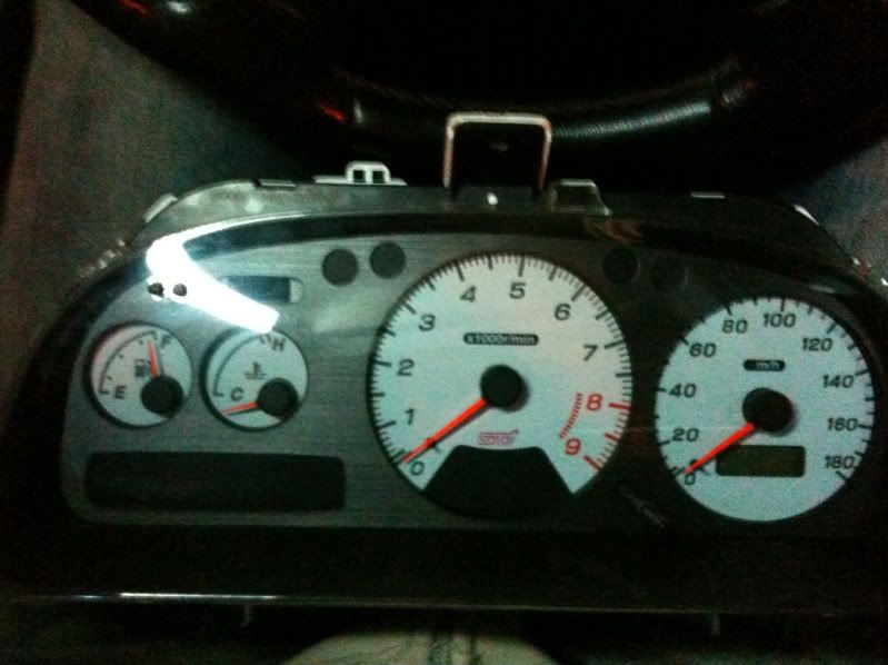
There are three connectors on the back, two on the left which you can ignore for this and one on the right. If you look at the back of the plug for the right hand side, where the cables go in, I've used the 2nd from the left, which is a black cable, shown here on top of the plug for clarity:
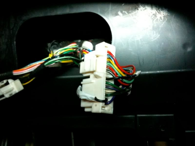
I've cut this cable, then connected the output of the convertor to the wire going to the plug and the input to the convertor is the one that goes back into the wiring loom.
I've soldered the connections as well - tried block connectors and the speedo went a bit ape ****, got a few pops and bangs on over-run and even a CEL! Soldered them and it was fine.
Last thing I found was to remove some of the wrap around the three wire bunches, to allow them to separate a bit more, which makes it a lot easier to get the plugs back in
Hope that helps a bit
Cheers
Pete
Firstly, just to make sure we are talking about the same clocks, here's a pic of mine:
There are three connectors on the back, two on the left which you can ignore for this and one on the right. If you look at the back of the plug for the right hand side, where the cables go in, I've used the 2nd from the left, which is a black cable, shown here on top of the plug for clarity:
I've cut this cable, then connected the output of the convertor to the wire going to the plug and the input to the convertor is the one that goes back into the wiring loom.
I've soldered the connections as well - tried block connectors and the speedo went a bit ape ****, got a few pops and bangs on over-run and even a CEL! Soldered them and it was fine.
Last thing I found was to remove some of the wrap around the three wire bunches, to allow them to separate a bit more, which makes it a lot easier to get the plugs back in
Hope that helps a bit
Cheers
Pete

Thread
Thread Starter
Forum
Replies
Last Post
Mattybr5@MB Developments
Full Cars Breaking For Spares
12
Nov 18, 2015 07:03 AM