

Charge temp sensor inlet mounting?

Thread Starter
Scooby Regular
iTrader: (10)
Joined: Jan 2008
Posts: 3,071
Likes: 0
From: Bedfordshire
Hi, I'm looking to get a charge temp sensor, and wondered if the blank on the inlet, to the right of the t/b in this pic would be a good place to tap it in? Saves drilling etc, and i can leave it alone when i go fmic.
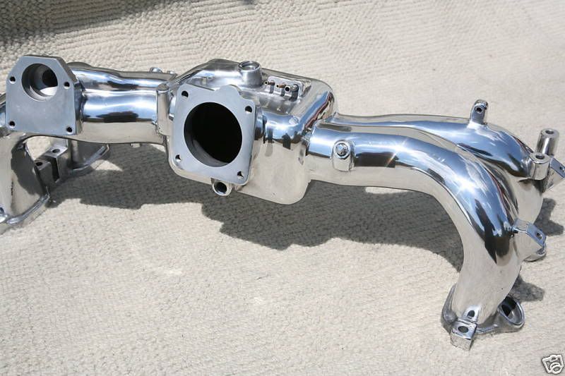
Thanks,Mit
Thanks,Mit
i think i read on here, if you put the sensor into the inlet it can asorb the heat from it.
i thought about putting it where the pcv valve goes if running the breathers to catch can mod
i thought about putting it where the pcv valve goes if running the breathers to catch can mod

Scooby Senior
iTrader: (3)
Joined: Jun 2006
Posts: 14,333
Likes: 0
From: Slowly rebuilding the kit of bits into a car...
You don't really want the sensor smack in the air flow, as that will reduce the reading !
A low flow zone would be better, like a corner of the intercooler, passenger side rear maybe, well away from the hot turbo and exhaust.
IMHO
dunx
A low flow zone would be better, like a corner of the intercooler, passenger side rear maybe, well away from the hot turbo and exhaust.
IMHO
dunx
well,its a good enough reading, easy enough to install and ives a good idea of air temp into the throttle body, i dont calculate anything from it so it doesnt matter if its 1-5 degrees different etc,just a good idea if i see a reading of 65 etc i know to back off

In the warm weather at the mo. I'm seeing 26-28c steady driving, off boost. Only recently installed, so no real idea of what it'll hit while giving it a bit of stick!
JohnD
Trending Topics

It's a pretty simple affair - might be worth looking in Maplins or similar electronics store, to be honest.
JohnD
Scooby Senior
iTrader: (3)
Joined: Jun 2006
Posts: 14,333
Likes: 0
From: Slowly rebuilding the kit of bits into a car...
But the airflow over the sensor makes the reading meaningless !
Would you install it in your vacuum cleaner hose, or it's body ?
WRC intake reaches 250 degrees ! pre-intercooler of course !
Makes a knocklink look sophisticated....
dunx
P.S. Some rudimentary mathematics would indicate that the air speed through the throttle body of my car at full boost and full revs is approaching 200 mph, so you might as well hang it out the window and do a top speed run. IMHO
Last edited by dunx; Jun 27, 2009 at 07:49 PM.
dunx,the temp at where my probe is is the temp of the air exactly after the intercooler,so it shows me pretty well what temp/how efficient my TMIC is, as it rushes thru the throttle body its not going to change temp by 50 degrees or so and im interested in the temp my Intercooler is working at, as the air passes over hotter parts yeah,its going to increase but not by much.
its an indication and works very well, if i had a blocked TMIC id know from the reading etc.
as said,its not a pinpoint exact measurement,thats getting **** but a good indication of my TMIC workings.
if the probe was in the throttle body the obsorbtion of heat from the metal would give false readings too so either way the readings are never going to be exact,but in the throttle body/tmic hose seems logical and from what i see,the more sort after and easier place to install


Got one of these mounted into my ashtray. You have to buy a voltage adapter to run from 5v to 12v (think thats what it is) this only costs a couple of quid.
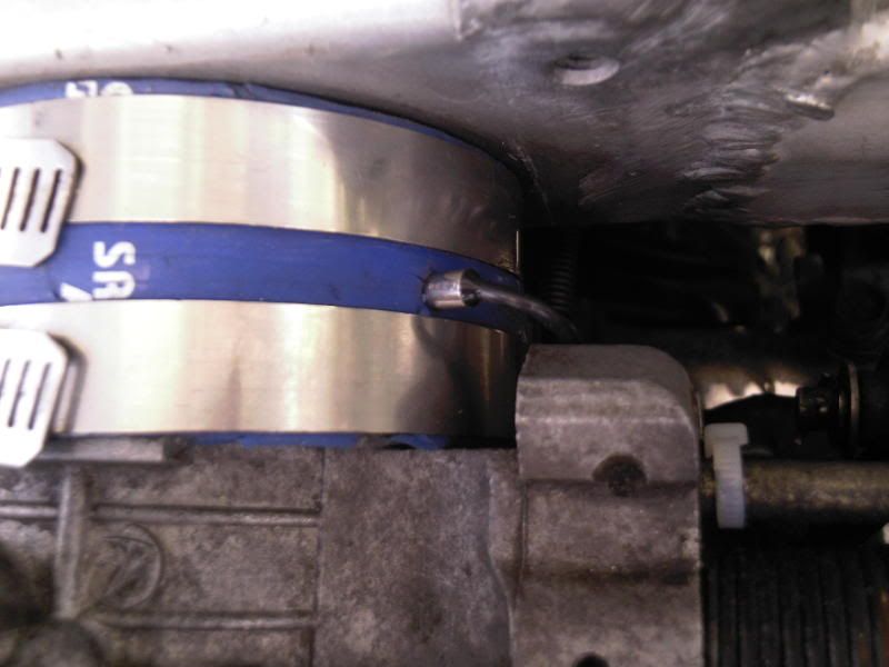
Extend the sensor wiring and I just put it between the intercooler and the throttle body, dont need to drill holes or nothing just poke it inder the jubilee clip into the pipe jobs agood un and cheap as chips.
WaterCooling UK - PC Water Cooling Shop and Forums | Home of Thermochill UK
This is the one.
WaterCooling UK: 12V - 5V Reducer Cable
Last edited by burbling1; Jun 27, 2009 at 11:22 PM.


Scooby Regular
Joined: Jul 2007
Posts: 676
Likes: 0
From: Newcastle
Got one of these mounted into my ashtray. You have to buy a voltage adapter to run from 5v to 12v (think thats what it is) this only costs a couple of quid.
Extend the sensor wiring and I just put it between the intercooler and the throttle body, dont need to drill holes or nothing just poke it inder the jubilee clip into the pipe jobs agood un and cheap as chips.
WaterCooling UK - PC Water Cooling Shop and Forums | Home of Thermochill UK
This is the one.
WaterCooling UK: 12V - 5V Reducer Cable
Cheers
Stew
Got my setup from the bay in the end.
my 1st one was from maplins, had it fitted 2 yrs but the probe broke,but they only do a 10 second refresh rate model now, so in the end i searched and found a place in hong long and paid �8 delivered and its better than any i saw on the market for �20+
Its powered by the cars 12v system too and no need for any resistors to be fitted,already all geared up for the 12v supply
bloke was very professional and it has a 2 second refresh rate
Last edited by The Rig; Jun 28, 2009 at 10:02 AM.
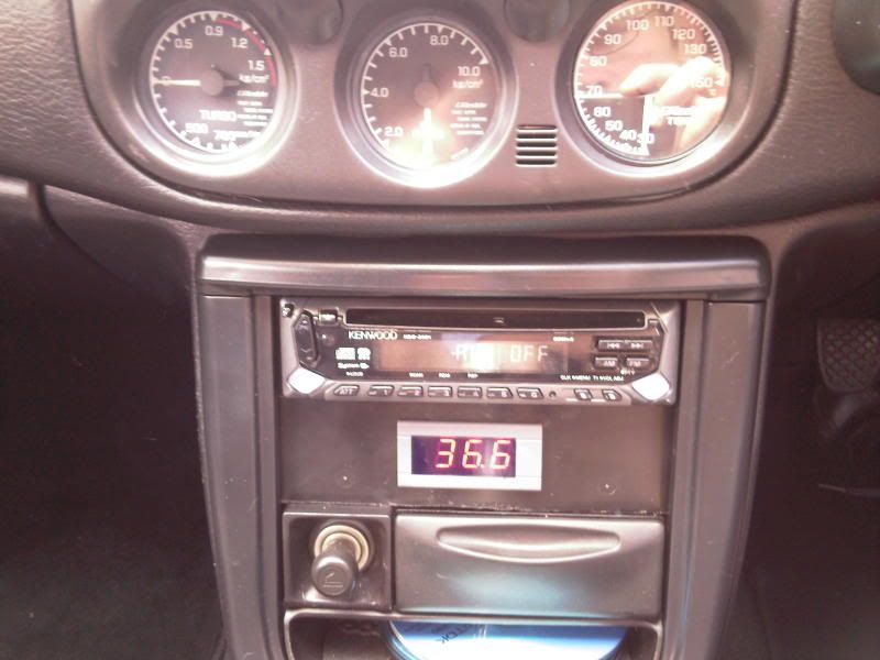
Rig, you've got a nice centre dash there (with the 3 dials in the heater panel  )... but the white surround of the LED temp gauge is letting it down.
Have you not thought of removing it, masking off the display and spraying the surround in satin black, then a clear coat laquer to seal in the paint? Do that, and it'll finish it off nicely...
)... but the white surround of the LED temp gauge is letting it down.Have you not thought of removing it, masking off the display and spraying the surround in satin black, then a clear coat laquer to seal in the paint? Do that, and it'll finish it off nicely...
Last edited by joz8968; Jun 28, 2009 at 11:09 AM.
Scooby Senior
iTrader: (3)
Joined: Jun 2006
Posts: 14,333
Likes: 0
From: Slowly rebuilding the kit of bits into a car...
A safe reading of an incorrect temperature is no use at all !
Please will somebody try a dual input gauge as suggested, to prove a point !
It's like reading EGT at the exit of your exhaust.
dunx
P.S. Mit has grasped this one, and has a better way than I, of indicating the errors involved.
P.P.S. This sort of error can bring down an aircraft, what chance does your Scoob have ?
Last edited by dunx; Jun 28, 2009 at 11:27 AM.
Dunx - what points need measuring and what type of sensors do you want using?
Mit has pasted up a windchill plot, which is a measure of the apparent air temperature on the skin of humans.
The air temperature is unchanged (sensor temp) with increasing wind flow - it is just that the "feel" of the air temp to a human is lower with an increase in wind flow, as more heat is removed from the skin by convection and evaporation.
The increase in wind speed has NOT altered the air temperature.
Where Mit wants to mount his sensor is the PCV valve, but if not used then its fine.
The newage Spec C has a charge temp mount in roughly the same place.
The sensor should be an insulated K probe or PT100 to avoid/reduce radiant heat transfer into its body.
The ideal charge temp reading point is in the combustion chamber - not quite a rig that an enthusiast can do.
Next best point is the inlet manifold, so long as the sensor isn't picking up heat energy from the manifold body.
The joiner hose offers an easy install and minimises radiant heat input.
Nick
Scooby Senior
iTrader: (3)
Joined: Jun 2006
Posts: 14,333
Likes: 0
From: Slowly rebuilding the kit of bits into a car...
dunx
P.S. So throttle body icing is not related to intake temperature and velocity then ?
Last edited by dunx; Jun 29, 2009 at 09:54 PM.
Stop chucking in spurious principles that have no bearing on the issue.
At the throttle, depending on how cracked open it is, there will be a velocity increase, pressure and temp drop and if high enough humidity then ice will form - but only on the throttle plate.
Once the charge gets past the throttle, velocity decreases, pressure and temp go back up to essentially pre-throttle conditions.
The charge then gets split four ways and assuming the sum of the four inlet tract cross section areas equal that of the throttle body, then the velocity and pressure are maintained to the inlet valve. Charge temperature may increase, depending upon what heat is picked up from the inlet tract walls and the charge velocity.
The IC is still a valid point for sensor mounting, if radiant heat input can be eliminated -but there is no reason to reject the following joiner tube as a valid location, as there is no sudden drop in charge temperature here.
BTW - windchill temps are a scientific interpretation (index) of the brains' perception of what the cold wind "feels" like. It is not an actual temperature at the skin surface.
Nick

Thread
Thread Starter
Forum
Replies
Last Post
Mattybr5@MB Developments
Full Cars Breaking For Spares
28
Dec 28, 2015 11:07 PM
Mattybr5@MB Developments
Full Cars Breaking For Spares
12
Nov 18, 2015 07:03 AM