When you click on links to various merchants on this site and make a purchase, this can result in this site earning a commission. Affiliate programs and affiliations include, but are not limited to, the eBay Partner Network.
Hi all. Sounds daft (I like the beep!), but I am making a little mono amp and speaker for the stock navi system on my 2007 UK Forester XT. When you replace the head unit with aftermarket the Navi no longer pipes sound to the speakers. Can anyone advise which pins on that went into the stock head unit are the Navi audio signal? I assume it's on the black connector that's now redudant. Cheers!
Thanks Don! The navi diagram was the one I was missing, but I still can't see the audio feed either from the navi unit (screen) or into the audio head unit! Unless it's diagram blindness...
it does not look like there's a simple solution, the navi unit maybe takes a feed from the head to indicate a state of readiness to recieve the audio signal. It's a level of electrical wizardary beyond me!
The black 8pin Sub Connector is used for the steering wheel satellite switch and the woofer output shown as i64 on the wiring diagrams (audio3). Although Subaru's numbering of the connector appears reversed (top row becomes 1,2,3,4; bottom row 5,6,7,8)(switch: pins 3/7; woofer: pins 4/8)
Page14 of manual
On pages 15/16 of the manual you have the SIE BUS connector (20 pin black) which shows pins 19 (navi gnd) and 20 (navi).
Pins 16,17 and 18 are also shown as audio (Lch, Gnd and Rch respectively) - amplifier feed?
Is this SIE BUS connector actually used in the original OEM setup?? As ive only seen images with the main white and small black used as per the wiring diagram.
Last edited by Don Clark; Nov 28, 2023 at 05:15 PM.
Yep, the 8 pin one I get. The 20 pin black had promising outs as you say, the promising ones do nothing on acc on (harness side). I wonder if there's a a signal required on some of the other ones. Bus + etc, to trigger the navi to send audio, or even if it's actually a digital signal. I tried to hard wire the stock unit to a battery 'on the bench' to get a multimeter on it but my little'n distracted me and I wired it backwards and probably blew it. 🤣 a fail of epic nature.
Last edited by Bazil_SW; Nov 28, 2023 at 06:32 PM.
The black 8pin Sub Connector is used for the steering wheel satellite switch and the woofer output shown as i64 on the wiring diagrams (audio3). Although Subaru's numbering of the connector appears reversed (top row becomes 1,2,3,4; bottom row 5,6,7,8)(switch: pins 3/7; woofer: pins 4/8)
Page14 of manual
On pages 15/16 of the manual you have the SIE BUS connector (20 pin black) which shows pins 19 (navi gnd) and 20 (navi).
Pins 16,17 and 18 are also shown as audio (Lch, Gnd and Rch respectively) - amplifier feed?
Is this SIE BUS connector actually used in the original OEM setup?? As ive only seen images with the main white and small black used as per the wiring diagram.
And yes the black 20 pin one is definitely plugged in for the stock kenwood unit.
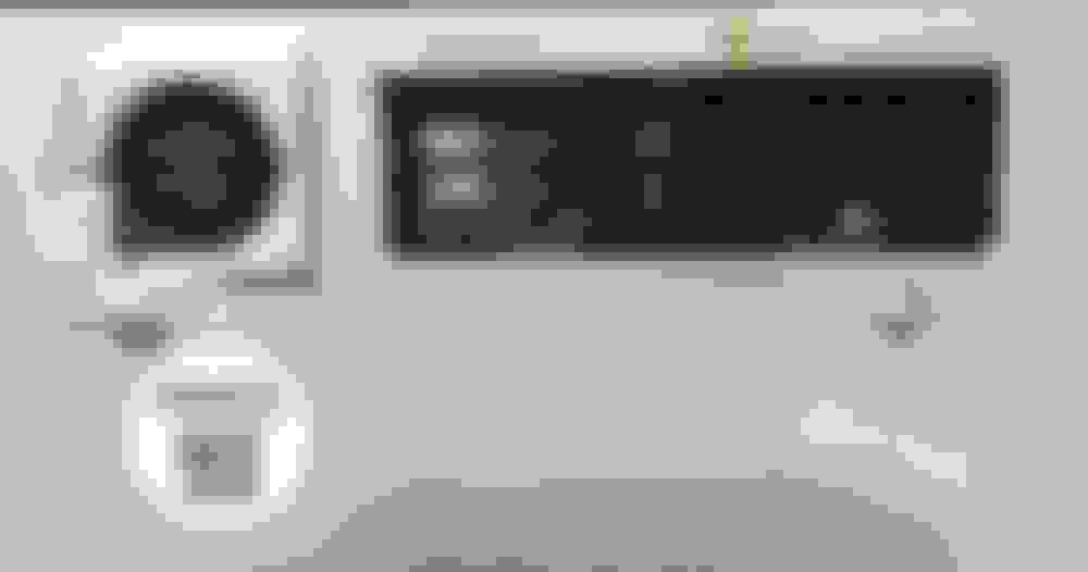
Just checked the info for the display unit and the mono audio out is sent from the 20 pin connector (pins numbered 17-36) and not the 16 pin main connector (i50) as detailed in the wiring diagrams.
This is shown on page2 of the following manual for the display unit. https://www.manualslib.com/manual/95...?page=2#manual
Back of Display unit
The link wire from the nav display to head unit is probably not shown on the Subaru wiring diagrams as it's most likely a kenwood supplied item as part of their fitting kit and is not considered a part of the main loom.
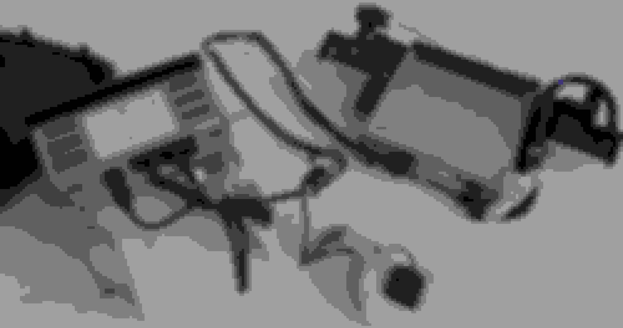
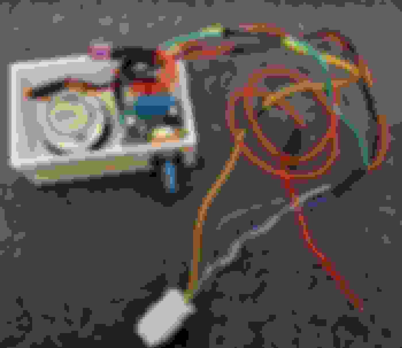
Complete nav unit with wire to head unit chopped
The two power supply cables shown are subaru cord assemblies 86273SA040 for the navi unit and 86273SA030 for the display unit which connect to (B274) and (i50) repectively
Last edited by Don Clark; Nov 28, 2023 at 09:20 PM.
Just checked the info for the display unit and the mono audio out is sent from the 20 pin connector (pins numbered 17-36) and not the 16 pin main connector (i50) as detailed in the wiring diagrams.
This is shown on page2 of the following manual for the display unit. https://www.manualslib.com/manual/95...?page=2#manual
Back of Display unit
The link wire from the nav display to head unit is probably not shown on the Subaru wiring diagrams as it's most likely a kenwood supplied item as part of their fitting kit and is not considered a part of the main loom.
Complete nav unit with wire to head unit chopped
The two power supply cables shown are subaru cord assemblies 86273SA040 for the navi unit and 86273SA030 for the display unit which connect to (B274) and (i50) repectively
Cheers Don. I tried to pull the navi screen hood off but one clip refused to give and I didn't fancy breaking it! From a quick glance at the wires though I'd say that second connector goes straight to the 20 pin on the back of the head unit so a feed should be possible there for the mono signal, but no joy. I think it might be a bust!
Assuming the 20 pin connector cable, that used to plug into the H/U is still in situ the mono signal will be on pin 20 and associated ground on pin19.
Looking at the display unit plug above it looks like pin 36 is a yellow cable which would be pin 20 on the H/U end.