Frayz's little tuning update..

Thread Starter

Joined: Sep 2005
Posts: 19,945
Likes: 2
From: "Engineering Perfection in Essex"
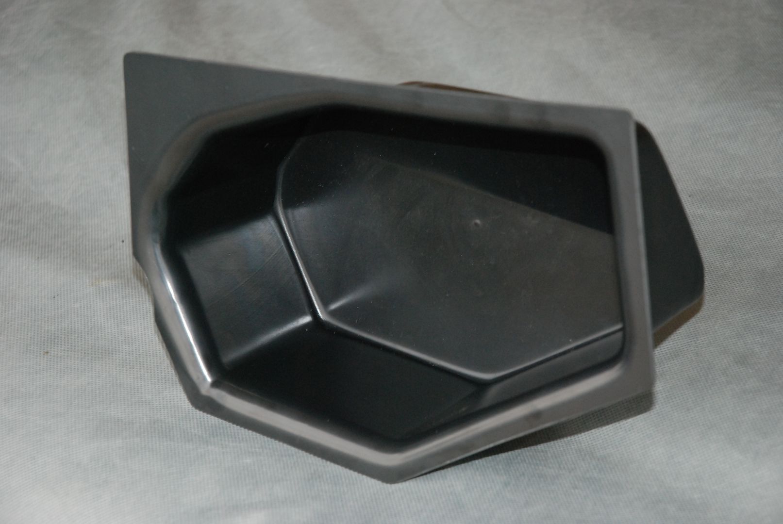
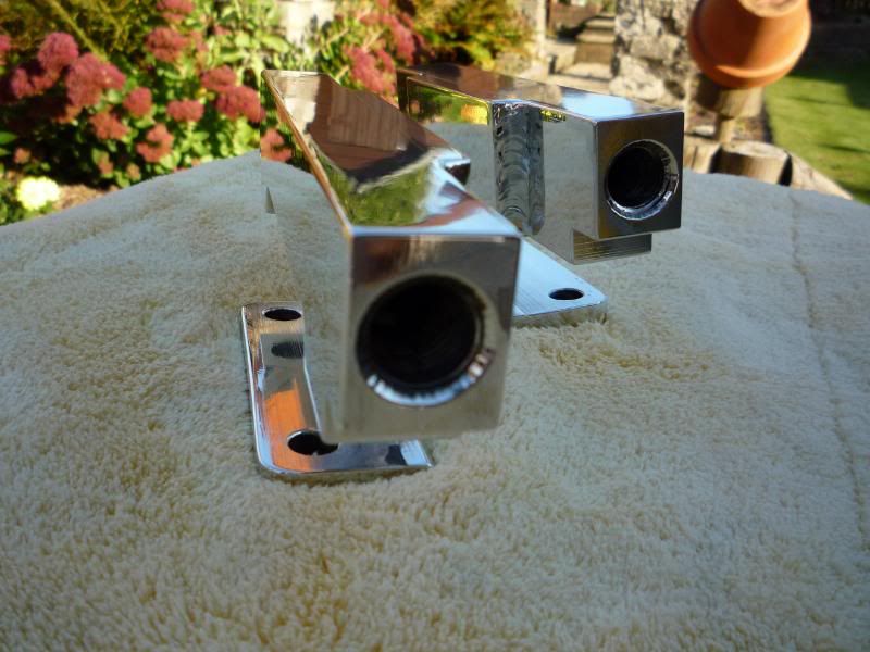
Proto #2 is ready to test fit. Numerous changes to this one but the finished article should look a lot more like this. This is only a rough one. The final will be much neater.
Please excuse the phone pic, I've uploaded this direct as I'm excited to show you all some development.

Please excuse the phone pic, I've uploaded this direct as I'm excited to show you all some development.


Thread Starter
Joined: Sep 2005
Posts: 19,945
Likes: 2
From: "Engineering Perfection in Essex"
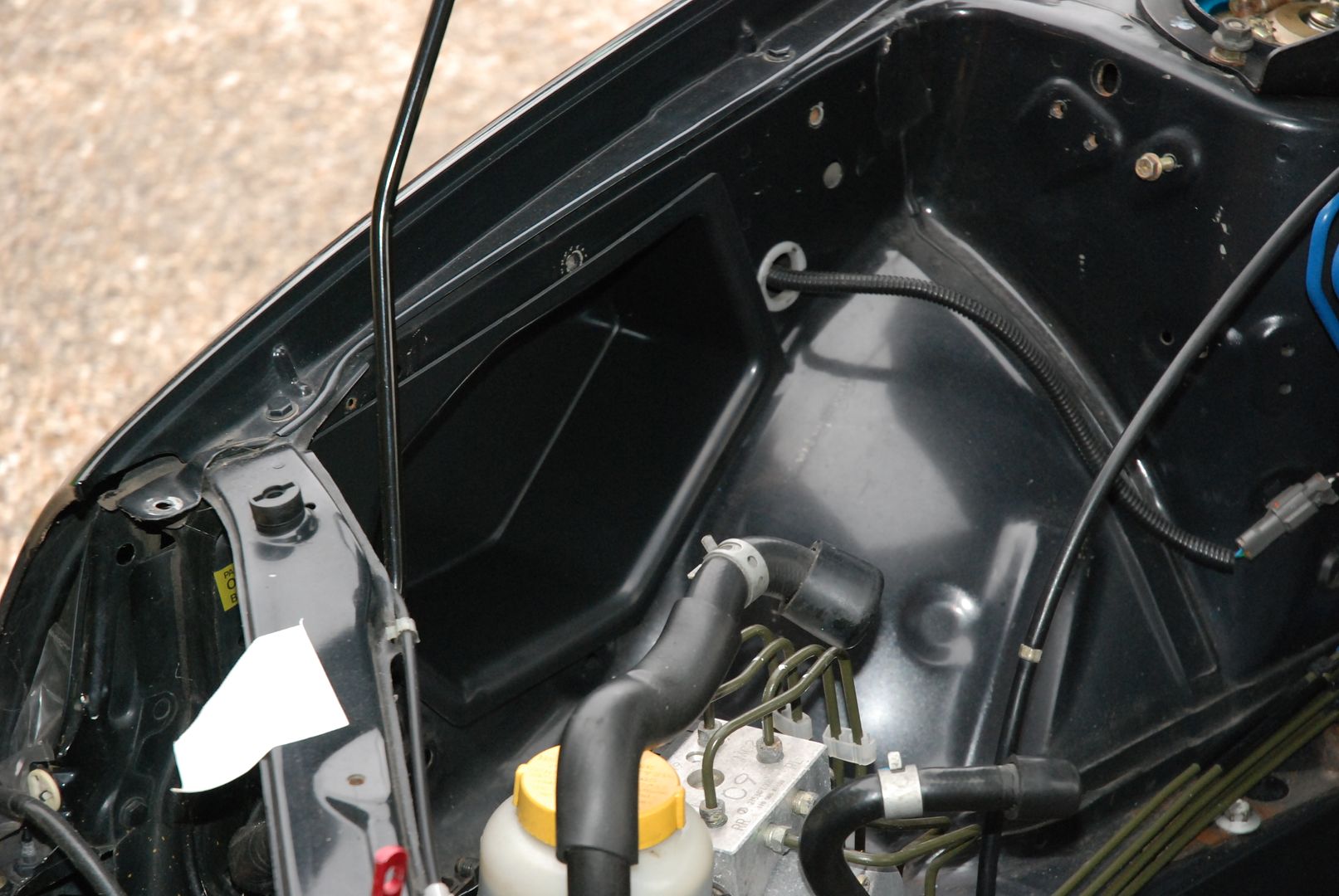
Okay guys, heres some snaps of proto #2 with a trail instalation. The fit this time is much much better.
Its now ready to have the air feed put in and then test fit once more.
Once the air feed is in and im happy we can go ahead and get a final one made up, cut tidy and actually installed.
Its amazing how much more room this provides for the air filter in the engine bay.
Its now ready to have the air feed put in and then test fit once more.
Once the air feed is in and im happy we can go ahead and get a final one made up, cut tidy and actually installed.
Its amazing how much more room this provides for the air filter in the engine bay.
Thread Starter
Joined: Sep 2005
Posts: 19,945
Likes: 2
From: "Engineering Perfection in Essex"
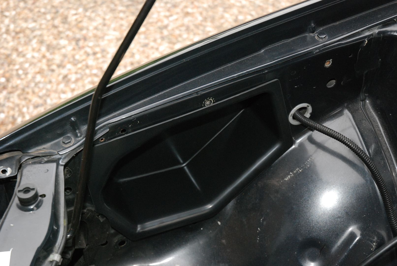
No mate, the air filter will be open. But will protrude into the wing pocket. The wing pocket will be fed directly from the front end via 83mm ducting. There willbe a huge volume of cool air forced into the vacinity of the air filter.
I do have some other ideas based on WRC designs but this is how it will be for now at least.
I do have some other ideas based on WRC designs but this is how it will be for now at least.

Page 53' FTW !
Looks really good Frayz Bit more elbow room
Is there any mileage in lipping the rear of the insert slightly to delay/disrupt the air longer in the vicinity of the filter ?
Looks really good Frayz
Bit more elbow room Is there any mileage in lipping the rear of the insert slightly to delay/disrupt the air longer in the vicinity of the filter ?
Thread Starter
Joined: Sep 2005
Posts: 19,945
Likes: 2
From: "Engineering Perfection in Essex"
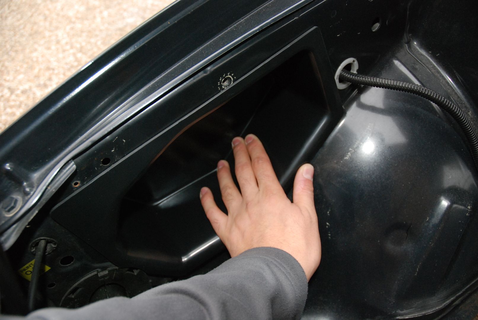
Good idea Stu but the insert is already shaped inside to force the air to swirl up and then out towards the filter. At the rate that air is consumed in that area i think its going to work really really nice.
The air has nowhere to go except towards the filter body.
Get your *** over here and look
The air has nowhere to go except towards the filter body.
Get your *** over here and look
Thread Starter
Joined: Sep 2005
Posts: 19,945
Likes: 2
From: "Engineering Perfection in Essex"
Sweet mate, drop by then.
Wouldnt mind a look at your classic to see if i can get one of these to fit?
If so then i might sell a few.
Wouldnt mind a look at your classic to see if i can get one of these to fit?
If so then i might sell a few.

Thread Starter
Joined: Sep 2005
Posts: 19,945
Likes: 2
From: "Engineering Perfection in Essex"
Sorry about the cak fone pic, but tonight i cut the hole for the turbo boost pipe. Im still going to modify the pipe bends so it fits a little cleaner but so far so good. This should keep the boost hose under the air filter and out of sight. Leaving the wingsert to do its job of just feeding in cold air to the filter without disruption or clutter from the boost pipework.


 These things take time you know!
Thread Starter
Joined: Sep 2005
Posts: 19,945
Likes: 2
From: "Engineering Perfection in Essex"
Not much to update at the mo guys as im waiting on a couple of parts before i can progress. Nothing major, just some fittings and hoses etc.
Also should have proto 3 of the wingsert made this week. This one should be almost bang on the final design providing there are no fitment issues. Its much easier for me to mess about getting it right before the motor gets dropped back in. Then believe it or not we can look to get the motor dropped back in. Im getting quite excited now its all looming closer.
Also, for all you facebookers, you can now follow the latest developments and custom parts by joining the frayz-engineering facebook group.
Here :
http://www.facebook.com/photo.php?fb...04000656333171
Also huge thanks to Mark (RB5 286) for taking the logo i designed and will be making me some small decals which should look like this
Last edited by frayz; Oct 26, 2010 at 07:46 PM.
Scooby Regular
iTrader: (2)
Joined: Feb 2003
Posts: 2,726
Likes: 0
From: 2.1 Spec-C .......Pimms O'clock!!
Well done Frayz, glad it's all coming together and your getting excited, the work you have put into it is awesome and will be great to see the car moving under it's own steam again
PS, loving the logo!
PS, loving the logo!
Thread Starter
Joined: Sep 2005
Posts: 19,945
Likes: 2
From: "Engineering Perfection in Essex"
Cheers Ross, i honestly dont think the pics really do it any favours. I think the motor looks epic on the stand as is...
Might build another just to look at
Might build another just to look at

Thread Starter
Joined: Sep 2005
Posts: 19,945
Likes: 2
From: "Engineering Perfection in Essex"

Scooby Regular
iTrader: (2)
Joined: Feb 2003
Posts: 2,726
Likes: 0
From: 2.1 Spec-C .......Pimms O'clock!!