When you click on links to various merchants on this site and make a purchase, this can result in this site earning a commission. Affiliate programs and affiliations include, but are not limited to, the eBay Partner Network.
This car is almost 20 years old and I have had it from new.
It has suddenly developed a fault and is over charging the battery @ 15.5 V, parking and battery lights are on.
It has a 23700AA390 A2TB2991 Alternator LS, I believe there may be possibly two different voltage regulators supplied in this same Alternator model, designation.
Two other Alternators have been tried one of the same type as original and a after market one, Same result, over charging.
The alternator has white wires to the B+ post and three wires, smaller gauge, in the plug in connector. These are coloured, Blue, Yellow and Black/White stripped.
Does anyone have wiring diagrams for this model year, Power, harness and ecu pinouts.
It is my understanding that one of these wire goes back to the ECU, one is through the ignition system and the other is a direct connection to the battery via a 10 Amp fuse( possibly Alt no 3)
I would appreciated any info someone could supply. I should say also the fault clear with original alternator the reappeared late. I have changed the battery lately to a Bosch s4 024( recommend) prior to that it had a Halfords battery. I have also retried it with the same Halfords battery, same issue.
I believe AGM battery's may cause issues with old cars.
For a MY99/00 UK classic Turbo 2000 (EJ205) the alternator you list is correct fitment and comes with a 23815AA140 voltage regulator.
The three wires to the plug are as you say Pin1 - Black/white; Pin2 - Yellow; Pin3 - BLue
However none of the early Impreza wiring diagrams (for what ever reason) show the BLue wire to the ECU (Earlier models have a 2 pin plug, no ECU connection)
Threaded connector
White wires are the main 12v power supply to system.
Green Plug
Black/white goes to the combination meter (dash) for the charge light and alternator excitation circuitry.
Yellow comes FROM the Battery via main fuse board.(no3 10A) to the alternator regulator control (Load feedback circuit)
Blue - From ECU ( additional Load regulator feed back - "Smart" alternator)
MY99/00 wiring diagrams for UK/European cars are hard to come by as the workshop manuals at the time where paper manuals, however the main "Power Supply Routing" is very similar in all Subarus.
MY98 with Grey 2 pin alternator plug
MY98 Charging light circuit
MY01 with Green 3 pin alternator plug (not showing the third wire)
It's not until the MY03 Forester workshop manual that the third circuit is shown (Load feedback circuit wiring colour different BLue/Red instead of Yellow) MY03 Forester green 3 pin plug
MY03 Forester Engine wiring showing " BLue generator wire from ECU"
However the ECU connection (Connector B136 Pin25) is not listed in the Foresters workshop manual ECU pinouts.
Pinouts for MY99/00 Impreza
If voltage regulator hasn't got any feed back (blown no:3 fuse) then main output will be high.
Last edited by Don Clark; 15 May 2019 at 02:22 PM.
First off I appreciate any help you can provide, and have done so.
The battery is out the car.
I stripped a short section of insulation from the three control wires, BLue, Black/white and Yellow.
If I am reading the power diagram correctly I would expect when testing continuity from the No3 fuse 10A, to the removed insulation section of yellow wiring, in the direction of the alternator to get an indication, if alls well, I didn't. The fuse is Ok checked that.
When I tried the same test on the Black/White stripped wire I did get continuity.
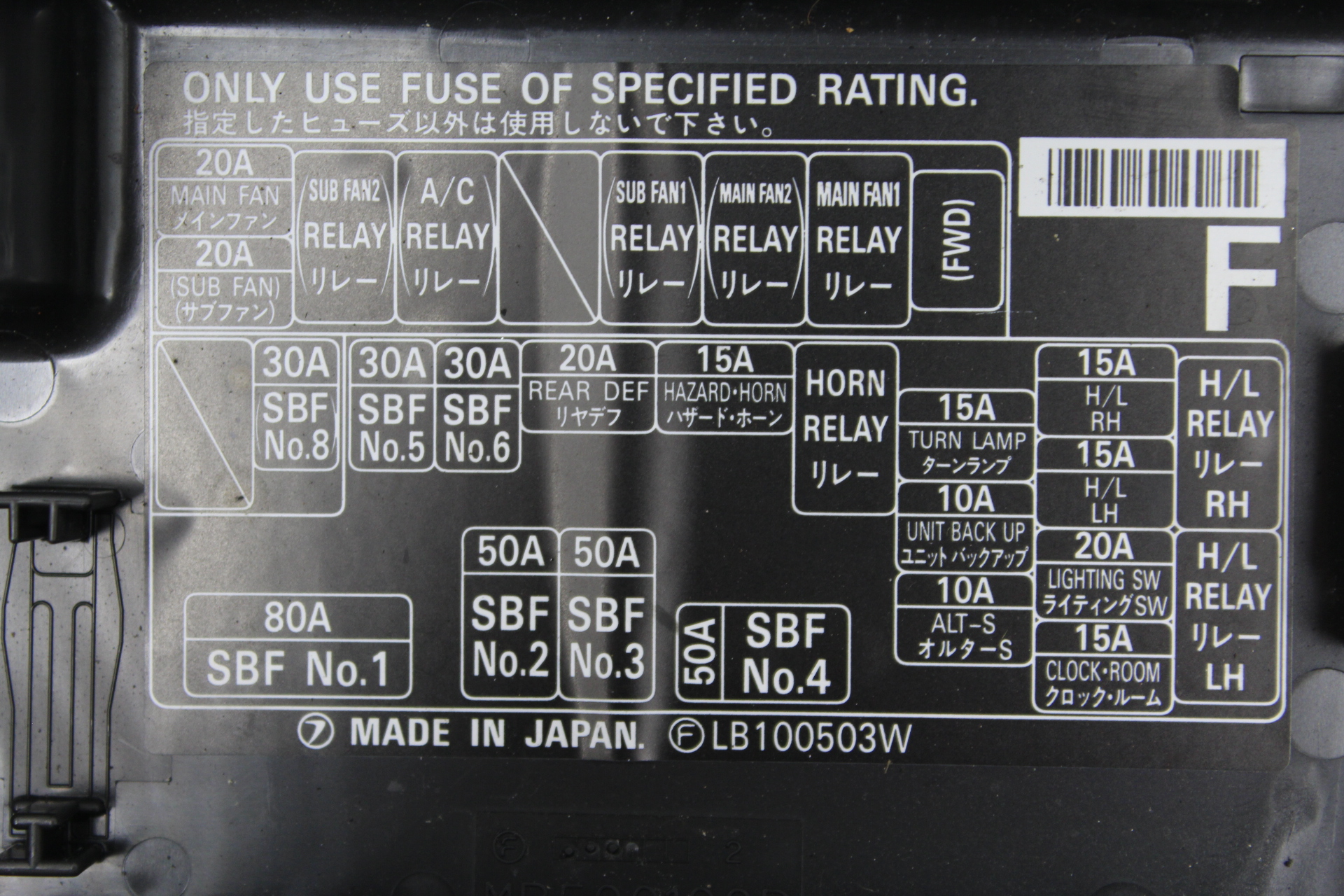
Which would suggest that the No3 Fuse in the main fuse box is not in the circuit of the Yellow line. It has 10A fuse in the main fuse box , ALTs underneath the cover indicating what it is for.
I believe there is another fuse box possibly around the passenger foot well.
I stripped a short section of insulation from the three control wires, BLue, Black/white and Yellow.
Why would you need to do that? - you could test via the green plug.
If I am reading the power diagram correctly I would expect when testing continuity from the No3 fuse 10A, to the removed insulation section of yellow wiring, in the direction of the alternator to get an indication, if alls well, I didn't. The fuse is Ok checked that.
If the fuse is OK - not just a visual check, as it's not always possible to see any break, then the easist way to test would be from the battery +ve terminal (battery is out of the car) to the green plug. When testing from the fuseholder to the alternator did you use the correct side of the holder as only one side of it connects to the alternator??
When I tried the same test on the Black/White stripped wire I did get continuity.
Which would suggest that the No3 Fuse in the main fuse box is not in the circuit of the Yellow line. It has 10A fuse in the main fuse box , ALTs underneath the cover indicating what it is for.
What are you actually saying? - that the B/W wire is connected to Fuse No3?? "ALTs" as a label in the fuse box lid is different to "ALT" (shown in a box) on the wiring diagrams.
You mean like this? ALT-S
I believe there is another fuse box possibly around the passenger foot well.
There is another fuse junction box but its by the drivers right knee.
Why would you need to do that? - you could test via the green plug.
If the fuse is OK - not just a visual check, as it's not always possible to see any break, then the easist way to test would be from the battery +ve terminal (battery is out of the car) to the green plug. When testing from the fuseholder to the alternator did you use the correct side of the holder as only one side of it connects to the alternator??
What are you actually saying? - that the B/W wire is connected to Fuse No3?? "ALTs" as a label in the fuse box lid is different to "ALT" (shown in a box) on the wiring diagrams.
You mean like this? ALT-S
There is another fuse junction box but its by the drivers right knee.
Hi Don,
Stripped the wire slightly to check if the issue was with the alternator plug. The wires in the plug are OK. Doesn't mean the connection to the alternator is but. Since It is a common fault with 3 Alternators, I have ruled that out for now.
I rechecked the continuity again in light of you comments. About which side of the fuse there is continuity to the B/W wire. Its the right hand side of the fuse.
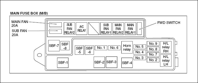
There is continuity from the battery lead to SBF-1 80A also to the right hand side of the fuse.
I have work out how to add pictures, not great a drawing though, The top of the picture is B/W, the other lines are Y and (Blue)L to the Alt connector.
My fuse box is the same as yours, see below.
The question I have now is since I didn't get continuity to the Yellow Line (2), from the opposite side of the fuse. Which according to the Power supply routing diagram I should get,
otherwise that fuse is not protecting anything ? Is this the problem "Bad connection" on the Yellow Line(2) simulating a blow fuse and, hence an overcharge ?
I did take a look at the other fuse box, nothing related to Alternator of charging circuit.
Hi Don,
This my ECM
Would I be right in thinking the connectors are numbered, from right to left, Blue 136, Grey 135 and Black 134, or is it reversed ?
Hi Don,
This my ECM
Would I be right in thinking the connectors are numbered, from right to left, Blue 136, Grey 135 and Black 134, or is it reversed ?
I believe the picture below looks at the pins of each of the ECU sockets. So Blue is B136, grey B135 and Black is B134
Hi Don,
Stripped the wire slightly to check if the issue was with the alternator plug. The wires in the plug are OK. Doesn't mean the connection to the alternator is but. Since It is a common fault with 3 Alternators, I have ruled that out for now.
I rechecked the continuity again in light of you comments. About which side of the fuse there is continuity to the B/W wire. Its the right hand side of the fuse.
There is continuity from the battery lead to SBF-1 80A also to the right hand side of the fuse.
I have work out how to add pictures, not great a drawing though, The top of the picture is B/W, the other lines are Y and (Blue)L to the Alt connector.
My fuse box is the same as yours, see below.
The question I have now is since I didn't get continuity to the Yellow Line (2), from the opposite side of the fuse. Which according to the Power supply routing diagram I should get,
otherwise that fuse is not protecting anything ? Is this the problem "Bad connection" on the Yellow Line(2) simulating a blow fuse and, hence an overcharge ?
I did take a look at the other fuse box, nothing related to Alternator of charging circuit.
The only thing left to look at on the Yellow wire link is the plug F39 in the base of the main fuse box to see if its corroded.
For the Black/white charge light circuit it is fed from fuse 18 in circuit FB13
If you trace back from this circuit on the Power Routing diagram (page 2)
to the main fuse board, both pass through Plug F39
So its possible that plug F39 maybe compromised giving you a reading on the Black and white wire to Fuse 3 or it could be any number of other circuits back feeding.
Remove fuse 18 from the fuse box under the dash and see if it still shows.
Potential fault Cable routing form Alt -> fise box and out through whepp arch harness Fusebbox and Yellow Alt cabel connetor female for underneath the fuse box. Potential fault location Fusebox Yellow cable connectoe male underneath fuse box.
Hi Don,
Gained access to the underside of the fuse box and disconnected the connector with the Yellow cable(Battery -> Alt)
Check the continuity back for the connector to the ALT connector. No continuity. Stripped back the harness and found what I suspect is the fault. Heavily corroded small section of cable (Green copper oxide)
I need to prove this out, splice the cable, but it looks promising. I suspect this why the Alt is overcharging, as you have mention previously.
I inspected the under side of the fused box where the connect is, no corrosive all the contacts look in good condition as does the spade connectors in the female connector.
The fused box looks to be a sealed unit so it is not possible as far as I can see to view the circuit an routing inside. I 'll check this again with a light. The spade connectors are reasonably spaced and I think it unlikely that I can continuity between the Blacl/white stripped cable is due to this connector. More likely as you have mentioned it is via a different route, particularly as the Black/White stripped cable is routed out in to the wheel arch and not into the fuse box
I will check this when I get a chance, as you mention by removing fuse 13.
As they say there is no I in team.
With out your help I would still be trying to work it out.
I'll let you know once I splice and test it. Still need to trace where the B(L)ue ECU cable enters the ECU, and confirm the issue with the Black/white stripped cable.
But is certainly is looking promising :-)
Additional wiring in Alt harness with 3 way connector
Hi Don,
Spliced the Yellow cable.
Fault was the cable had oxidised all the way through. This would explain why the fault had been intermittent originally.
Tested the B(L)ue cable back to the ECU, didn�t find a direct connection back to any of the ECU pin outs, on all three connectors.
Confirmed I did not have an issue with how I was doing it, by testing the Black/White stripped cable back to the ECU.
This circuit, Black/White stripped cable, would appear to be connect to the Black ECU connector. Picture shows the exact pin out I obtained continuity on.
Tested the solution. Voltage from the Alt across to the negative terminal is now 14.8V.
Battery light is now extinguished.
Electrically loaded the Alt, variation is between 13.9V->14.2V
Something I didn't mention previously is that this cable harness to the Alt, apart from the White x 2, B(L)ue, Black/White strip also has a B(Lue) cable terminated with three way connector, any ideas what it was intended for ?
Many thanks again for all you help with diagnosing this fault.
Glad you have sorted it and all back up and running at the correct voltage.
As I mentioned at the start, the manuals for these are few and far between and luckily due to the facelift for MY98 onwards, the few diags I have for that year have been useful (fuse box changed for MY98 onwards so was appropriate).
Looking at the MY98 diagrams the blue wired connector could very well be for the magnetic clutch of the A/C compressor - if fitted. (Pin1 - BLue)
The PIN out tables for the ECU only (usually) include those specific for engine sensors/connections so not surprised the other two only show in a round about way.
Any other ECU links only show up on specific circuit diagrams.eg, OE Immobiliser circuit, A/C system, Radiator Fan system.
Hi Don,
I suspect your correct about the additional connector, it being for the A/C. That was an option at the time I bought the car. It would have been an extract 1K pounds. And the dealers would have needed to fit it.
Looks like your well equipped for the 97model, .
I have put in a query about the regulator in the hope of getting some technical information about the one you mentioned that's fitted. Just in case the B(L)ue connection was for future versions, and the harnesses were manufactured with this in mind, or dual purpose for another vehicle. One after market supplier has N/A for the B(L)ue connection.
I saw somewhere that the B(L)ue ECU on an American 2.5 or 2,2 litre later versions, output from the ECU was 0->1 V ON or 10-13V off (Waveform), on Connector 84 on the ECU, mine has a space for this connector. I didn't get any reading when I tested the B(L)ue cable with the car running.
I find at bit odd they keep changing the wire colours for the same function.
I intend asking the suppliers of my vehicle if they would send me some info, Power supply, ECU pin outs, same as you have, but for this specific model and year of manufacture.
I might get lucky, with the car being so old now.
Long term I may need these.
I have not needed the information in the passed as all that has done to this car over the years is , replacement brake pipes, occasional service ( timing belt), replacement front calipers (car sat in the garage for 2 years, pots seized up "carbon steel", refurbished ones have stainless pots.
Just replaced back pneumatic struts on hatch, one failed.
It still has the original exhaust :-)
Best investment I made, as regards cars.
Also, you can tell they spend the money on the engineering, and not the interior fittings.
 14 May 2019, 07:51 PM