When you click on links to various merchants on this site and make a purchase, this can result in this site earning a commission. Affiliate programs and affiliations include, but are not limited to, the eBay Partner Network.
Don, that's absolutely great, especially with the pictures. So, one question arises. With the equilisation pipe in place, it would be my expectation that the pressure in the heads and the block should always be about the same. Now, if that were true, there wouldn't be a problem with connecting the crankcase breather to the header breathers or putting all 3 into the same catch can. Or am I wrong?
Don, that's absolutely great, especially with the pictures. So, one question arises. With the equilisation pipe in place, it would be my expectation that the pressure in the heads and the block should always be about the same. Now, if that were true, there wouldn't be a problem with connecting the crankcase breather to the header breathers or putting all 3 into the same catch can. Or am I wrong?
Nope, not a problem.
Although I use an AOS all my breathers are tee'd in together (as well as the oil filler pipe), leaving the PCV valve in place, for off boost conditions.
The line from the Y piece back to the turbo inlet pipe(#3) is replaced with a pipe that tees into the head line (as shown above) and the connection on the turbo inlet pipe blanked off
This then passes to the AOS which returns any oil dropout back to the sump (The oil filler effectively acting as both drain and additional head vent) and then the line returns to the other connection on the turbo inlet pipe.
To increase the surface area for oil to come out of suspension, I added a stainless steel mesh insert into the working chamber of the AOS (in a catch can stainless steel wool can be used).
Last edited by Don Clark; 21 February 2018 at 06:44 PM.
Hang on, so the crankcase vent pipe joins the pipe from the heads at the T-piece near the alternator and then the combined gas flows through the AOS system. The exit pipe then returns the cleaned gas back to the inlet. So, how is your PCV valve employed?
Hang on, so the crankcase vent pipe joins the pipe from the heads at the T-piece near the alternator and then the combined gas flows through the AOS system. The exit pipe then returns the cleaned gas back to the inlet. So, how is your PCV valve employed?
I see your point.
It only works because fresh air can be drawn down the filler neck to the head so maybe not with a catch can that returns to sump via the drain plug as that route is effectively blocked.
If the catch can has two separate feeds for the breathers then it would work more like OEM
OEM system
Vacuum condition
Boost condition
With filler neck AOS and tee'd pipes
Vacuum condition
Boost condition
Grimmspeed do one with the head and crankcase vents run separately to the AOS so would act more like OEM
Very useful diagrams again! Now then, to the nitty gritty. Under the vacuum condition with the OEM setup, the blowby gases in the crankcase are drawn out the vent and then taken through the open PCV valve into the intake manifold, along with some air direct from the intake. That's what the top diagram is showing.
Looking at the diagram with the AOS, the same thing is happening, i.e. air is coming from the inlet, through the AOS, along the pipe and is drawn into the PCV along with blowby from the crankcase. So that pipe running towards the turbo in your photo does have a tee in it since your diagram shows it going to the PCV as well as the crankcase. Yes?
Yes, the tee in that case is the fitting on the crankcase vent.
The hose on the right and the cap on the left replace pipe #3 below
Oh, so just to confirm, you didn't touch hose 6 or 11 in the diagram? Your pipe coming off the AOS system connects to the top of the OEM tee piece just below the turbo in the picture below. The pipe going to the PCV is untouched.
If that's your set up, I can see it would keep your turbo and IC clean, but under vacuum conditions with the PCV valve open, the gunk drawn out of the crankcase is still routed straight into the intake manifold to be burnt.
What I'm looking to do is to remove the OEM tee, take a pipe straight off the top of the block to the catch can, where the breathers from each head would also arrive, then the outlet from the catch can would return to the area in the picture above, with a new tee piece, connecting to the PCV and the intake (where you capped yours off). That arrangement then means the contents from the crankcase vent get cleaned prior to entering the intake via the PCV.
I might add, the reason for doing that is I'm trying to improve the combustion, not just keep the turbo and IC clean. I have very high carbon monoxide output at present. No chance of passing an MoT. Having done some research it appears that is indicative of poor combustion. I'm also going through a lot of oil and I know the PCV is to blame.
That's how I have my RCM three port plumbed in, except having let the can fill up for a while without the sump return fitted I decided it was a bad idea because there was foul smelling liquid and mayonnaise in there. So I have to drain the can regularly. Going to come up with a valve of some sort and a piece of pipe so I can just stick something under the car and open a valve to drain it.
That's how I have my RCM three port plumbed in, except having let the can fill up for a while without the sump return fitted I decided it was a bad idea because there was foul smelling liquid and mayonnaise in there. So I have to drain the can regularly. Going to come up with a valve of some sort and a piece of pipe so I can just stick something under the car and open a valve to drain it.
I agree. Having seen the youtube videos showing the contents of a catch can, I don't want that returned to my oil system!! I'm intending to buy a catch can with a drain **** and a level indicator and as big as will fit in the space. Hoping not to go down the RCM route though. Pricey for what it is.
Okay, so I wanted a catch can system that retained the PCV and intake connections to keep the crankcase under a vacuum under off-boost conditions in order to draw out the combustion products positively. My system design was based on a 3 port can from OBP motorsports with 15mm spigots. All hoses and connectors came from autosiliconehoses.com.
I designed a bracket to mount the catch can to the nearside strut tower using the existing two spare 6mm bolt holes. The slots in the bracket permit the position of the catch can to be adjusted vertically during installation. The bracket was made by a local engineering firm but unfortunately they didn’t get it right and drilled the holes in the wrong place (very annoying) but it still fitted.
Then it was off to Subaru4You in Newbury for the install (and some other bits and pieces). The problem with my design, particularly the 19mm hose for the PCV and crankcase connections, is a lack of space to route the piping. The other issue is how efficient the catch can is. If it doesn’t condense the oil vapours well, you still end up pushing oil back into the intake and inlet manifold via the return pipe. This led to a long discussion with Len about the merits of positive crankcase ventilation and whether it was needed. On balance it was considered that ensuring the intake and manifold stayed free of oil was the priority and that therefore the best solution was to cap off the PCV and both intake connections and vent the catch can to atmosphere.
And Len pointed out something else I hadn’t realised and I’ve not seen written elsewhere. The balance pipes that run between the heads and crankcase (see diagrams earlier in this thread) are intended to transfer excess oil from the heads back to the crankcase. This is particularly important under hard cornering when oil can build up in the heads. It is essential that the breather pipes are set higher up than the balance pipes, otherwise the excess oil ends up in the breathers. This is why the OEM head breather pipe runs across the front of the intercooler – it’s high up by design.
So, after all my design work, a major redesign using what we had available.....
The PCV valve was blocked off using a 16mm end cap.
The spigot on the intake duct for the head breather return pipe was blocked off using another 16mm end cap and the pipe removed.
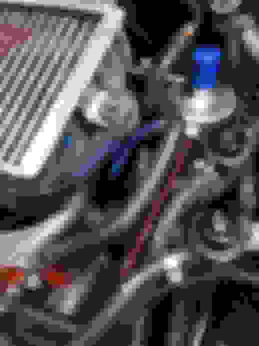
The offside head breather pipe was left in position (blue pipe). The nearside head breather pipe was removed and connected to the top of the OEM T-piece directly above the crankcase breather spigot (red pipe). The spigot on the intake duct for the crankcase breather was blocked off using a 12mm end cap (green dot). The pipe connecting the OEM T-piece to the PCV valve was blocked off.
The intercooler was put back on and the offside head breather pipe (blue) and crankcase breather pipe (red) were connected to the metal head breather piping on the front of the intercooler. All looks very OEM!
Moving to the other side of the engine bay, with catch can mounted, a 19-16mm reducer pipe is connected to the rear spigot. A T-piece on the other end diverts the outflow from the can downwards via a 19mm pipe to vent underneath the car. The top vent on the catch can is blocked off with a 20mm end cap but will be used to draw out the contents of the can by syringe.
With the intercooler back on, the spare head breather return pipe was used to connect the breather pipe from the crankcase and offside head to the catch can on the centre spigot (blue pipe). 13mm silicone hose was used to connect the nearside head breather direct to the front spigot of the catch can (red pipe).
So now I have an install which is pretty low-key. Obviously the catch can is visible but the only new piping you can actually see is for the nearside head. All the other piping is re-used OEM. It’s all rather tidy.
Issues: The crankcase and offside head breathers both use the intercooler pipe work. There is a concern that the pipe is only 10mm inside diameter which is not really enough. Len thinks it should be okay for road use, but you’d want a bigger pipe for track days since the flow will be much greater. I do have a plan to look at feeding the offside head and crankcase pipes into a 16mm silicon hose and running that to the catch can at which point the intercooler pipe will be redundant.
Last edited by David__H; 29 March 2018 at 08:37 PM.
If that is a baffled OBP tank unless your using the top connector to return to the engine intake you are wasting your effort, as the 3 side connectors are on the same side of the baffle plate, hence you will not get air / oil separation.
If that is a baffled OBP tank unless your using the top connector to return to the engine intake you are wasting your effort, as the 3 side connectors are on the same side of the baffle plate, hence you will not get air / oil separation.
So why have you capped the outlet that's on the other side off the baffle plate, you are gaining nothing by how you have the return piped up.
When I bought the can the guy at OBP motorsports said the top spigot was just for venting to atmosphere and that if routing back to PCV/intake I would be using the "outlet" spigot on the side and the top spigot should be capped off. I therefore assumed that the baffle inside must separate one of the spigots on the side from the other two such that there were two inlet connections and one outlet. I bought the pipework based on that expectation. Having got the can I discovered that the baffle is as you describe, i.e. all 3 spigots on the side feed in to the same part of the can.
Now, as it happens, because the installation plan changed and I am venting to atmosphere, there is no return pipe and hence no vacuum drawing the gases from the can. Therefore (I believe) it's not so likely for the inlet gases to be drawn straight out down the vent. At least, that's how I see it. I'm going to monitor what the can catches. If it doesn't fill up it definately isn'ty working, at which point I will move the vent pipe onto the top spigot and see if it makes a difference.
why do expect it to fill up either way. Were you having problems beforehand with oil coatings on the inside of breather pipes/ turbo intake/ intercooler?
Trev
That's how I normally fit the catch can on Hawkeye's, the top connection is always vent to atmosphere or return to inlet, with the pcv plugged.
what would the cost be for you to supply and fit that to a hawkeye sti with a front mount? ive messaged 2 very well known tuners about supply and fit a catch can but not one of them has bothered to reply
That's how I normally fit the catch can on Hawkeye's, the top connection is always vent to atmosphere or return to inlet, with the pcv plugged.
Nice. I struggled to mount the can in that position, but I definately looked at putting it there. I'm gonna order a 22mm to 19mm reducer elbow from ASH and fit it to the top like you have and attach that to my vent tube. I can then run a pipe straight from the crankcase to the catch can.
why do expect it to fill up either way. Were you having problems beforehand with oil coatings on the inside of breather pipes/ turbo intake/ intercooler?
Trev
Yes, I'm using a litre of oil every 1500 miles, which is okay, but I get blue smoke on start up sometimes and the turbo and IC are coated oil. I can poor it out the IC.
Yes, I'm using a litre of oil every 1500 miles, which is okay, but I get blue smoke on start up sometimes and the turbo and IC are coated oil. I can poor it out the IC.
that's bad for the oil to be fouling that much of the system. It'll be interesting to see where it all comes from. I can understand it coming from a hard launch start where the oil surges and comes in direct contact with the crank breather but sounds like it could be heads and crank.
Good luck there, will certainly follow the thread
Trev
 21 February 2018, 06:19 PM


 I agree. Having seen the youtube videos showing the contents of a catch can, I don't want that returned to my oil system!! I'm intending to buy a catch can with a drain **** and a level indicator and as big as will fit in the space. Hoping not to go down the RCM route though. Pricey for what it is.