
WIRING DIAGRAM FOR AUTO HAWKEYE


Thread Starter
Scooby Newbie
Joined: Jul 2018
Posts: 11
Likes: 0
From: Johannesburg
Hi guys,I really need help! I'm looking for a wiring diagram spefically for my auto-hawkeye. My VIN # is GDA-021127. My speedo won't work and the car wont go over 4000rpm. Took it to en electrician who says the wiring diagram he has shows 2 wires that go into my instrument cluster but my car only has 1. I've had this problem for a while now because nobody seems to be able to figure the wiring out. Please help!
Scooby Regular


Joined: Feb 2003
Posts: 7,816
Likes: 824
From: Harpenden
Probably because it's a JDM (Japanese Domestic Model) Sport Shift (SS below) model, manufactured in February 2007 (0702 below) import rather than a North American (NA) or "Rest of the World" (RW) model.

Wiring diagrams for JDM models are almost nonexistent (for public consumption) outside of Japan and their wiring systems are usually a year or two ahead of the other model areas with NA next, followed by RW.
Also, AFAIK Sportshift Turbocharged engine models were JDM and NA only.
Ignoring the turbo part,both the NA and RW diagrams for the combination meter show a single input for the speedo.
As it's an automatic model the speed signal is taken from the TCM (Transmission Control Module) - no external MT vehicle speed sensor fitted.
MY06/07 RW AT control circuit

however the speedo wiring circuit has been separated out.............
MY06/07 RHD RW models

unlike the NA version
MY06/07 NA models AT controls (speedo circuit included)

NA Combination meter

As the Auto box has internal speed sensors it's possible that the loom from the Autobox to TCM is damaged in some way and the TCM is not receiving the speed signal required which may also be why you cannot go over 4000rpm.
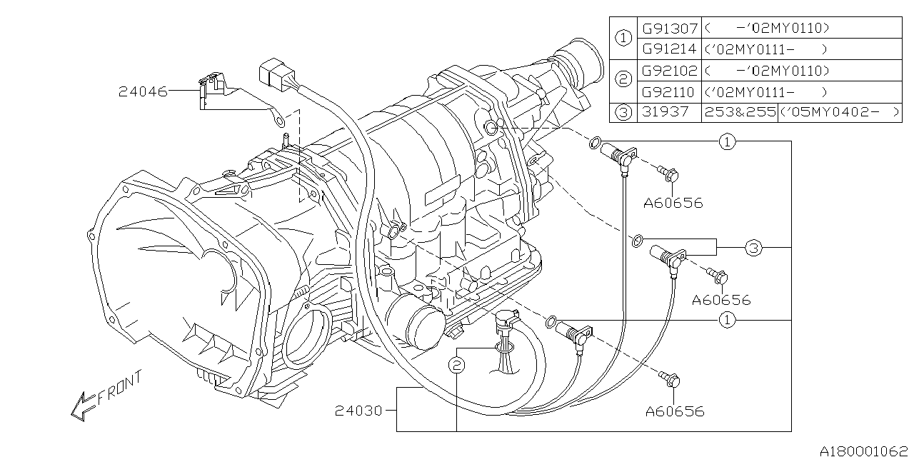
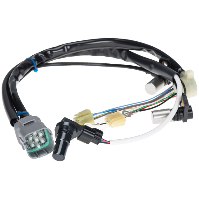
Current part number listed for GDA-021127 is SENSOR AND HARNESS ASSEMBLY TRANSMISSION 24030AA072 (previous 24030AA071; 24030AA070)
Wiring diagrams for JDM models are almost nonexistent (for public consumption) outside of Japan and their wiring systems are usually a year or two ahead of the other model areas with NA next, followed by RW.
Also, AFAIK Sportshift Turbocharged engine models were JDM and NA only.
Ignoring the turbo part,both the NA and RW diagrams for the combination meter show a single input for the speedo.
As it's an automatic model the speed signal is taken from the TCM (Transmission Control Module) - no external MT vehicle speed sensor fitted.
MY06/07 RW AT control circuit
however the speedo wiring circuit has been separated out.............
MY06/07 RHD RW models
unlike the NA version
MY06/07 NA models AT controls (speedo circuit included)
NA Combination meter
As the Auto box has internal speed sensors it's possible that the loom from the Autobox to TCM is damaged in some way and the TCM is not receiving the speed signal required which may also be why you cannot go over 4000rpm.
Current part number listed for GDA-021127 is SENSOR AND HARNESS ASSEMBLY TRANSMISSION 24030AA072 (previous 24030AA071; 24030AA070)
Thread Starter
Scooby Newbie
Joined: Jul 2018
Posts: 11
Likes: 0
From: Johannesburg
HI, so the electrician has requested for the instrument cluster pin out diagram and the ECU/TCU pin out diagram. He says he needs those too. Could you help?
Scooby Regular
Joined: Feb 2003
Posts: 7,816
Likes: 824
From: Harpenden
As previously mentioned JDM wiring diagrams are almost non existant outside of Japan.
Also as stated previous diagrams were for the European (RW) and North American (NA) models and as such should only be used as a guide as JDM models can have different equipment fitted and also different wiring colour schemes.
One major difference between the European and JDM cars is that the JDM is equipped with a Body Integrated Unit which centralises many of the electrical processes e.g. interior and exterior lighting systems, seat belt warning system, headlight levelling system, and many more.
Below are the requested files which are only appropriate for the European (2.5L) turbo engine with normal (non luminescent) combination meter many of the inputs being different to JDM, but maybe useful in your quest.
ECU i/o signal pdf
TCM i/o signal pdf


Thread
Thread Starter
Forum
Replies
Last Post