Audi quattro 6 sp impreza conversion
 14 October 2014, 11:19 AM
#91
Scooby Regular
iTrader: (3)

Join Date: Sep 2013
Location: Newcastle upon Tyne
Posts: 78
Likes: 0
Received 0 Likes
on
0 Posts
This would be quite an elegant solution - interested to know what you're doing about the speedo?
Really great to read threads like this, certainly makes a change from the norm. If you want a hand with any of the electronics for the speedo I'd be more than happy to help. Although judging by your practical skills I doubt you'll need it anyway!
Really great to read threads like this, certainly makes a change from the norm. If you want a hand with any of the electronics for the speedo I'd be more than happy to help. Although judging by your practical skills I doubt you'll need it anyway!
 14 October 2014, 01:21 PM
#92
Scooby Regular
Thread Starter

This would be quite an elegant solution - interested to know what you're doing about the speedo?
Really great to read threads like this, certainly makes a change from the norm. If you want a hand with any of the electronics for the speedo I'd be more than happy to help. Although judging by your practical skills I doubt you'll need it anyway!
Really great to read threads like this, certainly makes a change from the norm. If you want a hand with any of the electronics for the speedo I'd be more than happy to help. Although judging by your practical skills I doubt you'll need it anyway!
I have read that the impreza produces 4 pulses per rev, assuming it's revs of the speed sensor, the speed sensor turns once for every four revs of the prop (so wheel speed basically) the audi has four magnets on the output side of the front diff, so again four pulses per rev of the wheel (assuming I'm right about the imprezas sensor giving four pulses per rev)
A hall sea or having a Vref, earth and signal wires I am hoping to just connect to the Vref and signal through the reed switch and see if it works and how close it is.
14 October 2014, 04:56 PM
#93
Scooby Regular
iTrader: (3)
Join Date: Sep 2013
Location: Newcastle upon Tyne
Posts: 78
Likes: 0
Received 0 Likes
on
0 Posts
So does the audi box definitely have a reed switch sensor not a variable reluctance/VR sensor?
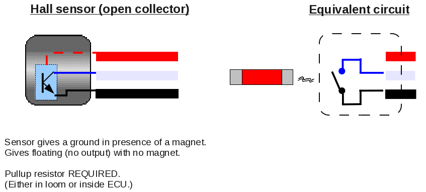
If so, I think the reed switch will need to go between the signal and earth wires. Hall sensors are used in an open collector arrangement which requires a pull-up resistor to get a voltage change at the output:
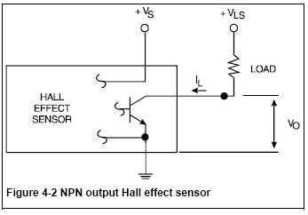
As long as both systems produce the same number of pulses per revolution it should work.
If so, I think the reed switch will need to go between the signal and earth wires. Hall sensors are used in an open collector arrangement which requires a pull-up resistor to get a voltage change at the output:
As long as both systems produce the same number of pulses per revolution it should work.
 14 October 2014, 09:18 PM
#95
Scooby Regular
Thread Starter
Yeah apparently it's a reed switch, bizare I know. I will double check it with a meter once I've finished grinding and welding.
I'll take on board what your saying about the sig+earth, I'll poke the wires in those holes first, see what happens. Thanks
I'll take on board what your saying about the sig+earth, I'll poke the wires in those holes first, see what happens. Thanks
15 October 2014, 11:46 AM
#97

So does the audi box definitely have a reed switch sensor not a variable reluctance/VR sensor?
If so, I think the reed switch will need to go between the signal and earth wires. Hall sensors are used in an open collector arrangement which requires a pull-up resistor to get a voltage change at the output:
As long as both systems produce the same number of pulses per revolution it should work.
If so, I think the reed switch will need to go between the signal and earth wires. Hall sensors are used in an open collector arrangement which requires a pull-up resistor to get a voltage change at the output:
As long as both systems produce the same number of pulses per revolution it should work.

If number of pulses/per rev is incorrect a cmos divider or multiplier circuit is cheap as chips and works well (in my experience), no need to go down the microcontroller route which is more costly and complex unless you can write the required code
15 October 2014, 02:15 PM
#98
Scooby Regular
iTrader: (3)
Join Date: Sep 2013
Location: Newcastle upon Tyne
Posts: 78
Likes: 0
Received 0 Likes
on
0 Posts
Agree with the above, nice easy solution as long as you are dividing/multiplying by an integer amount. If you were using a different differential ratio for example (i.e. not 4.11:1) you need to get a bit more creative - that's where a microcontroller can be handy.
15 October 2014, 02:28 PM
#99
Scooby Regular
Thread Starter
Or I can always mount magnets on the driveshaft flanges and a hall sensor on the gearbox.
Any links to these controllers? Interested in the easiest/cheapest solution. Thanks
Any links to these controllers? Interested in the easiest/cheapest solution. Thanks
15 October 2014, 03:57 PM
#100
Scooby Regular
Thread Starter
Last night I started to the exhaust, the rear silencer was almost a straight fit, only needing te front hanger dropped a little to clear the diff, this has in fact made my prodrive back box sit better, as the tailpipe was pointing down previously.
The centre section has been cut and will be welded in a slightly different position, to allow for the angle difference on the rear silencer. Front pipe needs similar modification just to clear the bottom of the gearbox, cut, twisted and welded. This has resulted in the exhaust being 1/2" closer to the ground, not really a problem as there is still miles of clearance on my car.
Hopefully have it welded/bolted on tonight, then it's just the starter and Intercooler to mount and it's ready for a startup and run through the gears in the air. Saturday should be the day
15 October 2014, 05:41 PM
#101
Scooby Regular
iTrader: (2)
Join Date: May 2010
Location: Brecon, Mid Wales
Posts: 1,909
Likes: 0
Received 0 Likes
on
0 Posts
Last night I started to the exhaust, the rear silencer was almost a straight fit, only needing te front hanger dropped a little to clear the diff, this has in fact made my prodrive back box sit better, as the tailpipe was pointing down previously.
The centre section has been cut and will be welded in a slightly different position, to allow for the angle difference on the rear silencer. Front pipe needs similar modification just to clear the bottom of the gearbox, cut, twisted and welded. This has resulted in the exhaust being 1/2" closer to the ground, not really a problem as there is still miles of clearance on my car.
Hopefully have it welded/bolted on tonight, then it's just the starter and Intercooler to mount and it's ready for a startup and run through the gears in the air. Saturday should be the day
The centre section has been cut and will be welded in a slightly different position, to allow for the angle difference on the rear silencer. Front pipe needs similar modification just to clear the bottom of the gearbox, cut, twisted and welded. This has resulted in the exhaust being 1/2" closer to the ground, not really a problem as there is still miles of clearance on my car.
Hopefully have it welded/bolted on tonight, then it's just the starter and Intercooler to mount and it's ready for a startup and run through the gears in the air. Saturday should be the day
 16 October 2014, 10:52 AM
#105
, the way I work with these is as follows, for tacho I use a timing light (or ecu data) to find correct rpm, then work out the correction factor and build circuit to suit for speedo I use a tomtom to get correct speed. Deej is correct that these will not work in all situations. I buy my components from Bitsbox, If you do have a problem and are struggling with the data sheets (which imho are about as clear as mud), pm me I will sort you out a cct diagram. Arduino (uno) is about the simplest microcontroller there is loads of info about for these, I am fairly new to micros myself and hopeless (very slow) at coding
16 October 2014, 11:08 AM
#106
Scooby Regular
Thread Starter
These are cmos ic's, eg cd4011, cd4017 I work from data sheets. The cct is very simple just a couple of resistors and capacitors, no need to worry about voltage , the way I work with these is as follows, for tacho I use a timing light (or ecu data) to find correct rpm, then work out the correction factor and build circuit to suit for speedo I use a tomtom to get correct speed. Deej is correct that these will not work in all situations. I buy my components from Bitsbox, If you do have a problem and are struggling with the data sheets (which imho are about as clear as mud), pm me I will sort you out a cct diagram. Arduino (uno) is about the simplest microcontroller there is loads of info about for these, I am fairly new to micros myself and hopeless (very slow) at coding
, the way I work with these is as follows, for tacho I use a timing light (or ecu data) to find correct rpm, then work out the correction factor and build circuit to suit for speedo I use a tomtom to get correct speed. Deej is correct that these will not work in all situations. I buy my components from Bitsbox, If you do have a problem and are struggling with the data sheets (which imho are about as clear as mud), pm me I will sort you out a cct diagram. Arduino (uno) is about the simplest microcontroller there is loads of info about for these, I am fairly new to micros myself and hopeless (very slow) at coding
17 October 2014, 08:54 AM
#108
This is a great conversion but I very much doubt it will effect the price of STI 6 speed boxes and conversion kits. The STI setup is far easier than this conversion, no real engineering required compared to this great job being done.
Keep up the fine work man!
If you make a conversion kit for these Aubaru systems then people may be interested.
Keep up the fine work man!
If you make a conversion kit for these Aubaru systems then people may be interested.
17 October 2014, 09:12 AM
#109
Scooby Regular
Thread Starter
I await someone else doing a conversion like this, but remember where you saw it first!
17 October 2014, 09:15 AM
#110
Scooby Regular
Thread Starter
This is a great conversion but I very much doubt it will effect the price of STI 6 speed boxes and conversion kits. The STI setup is far easier than this conversion, no real engineering required compared to this great job being done.
Keep up the fine work man!
If you make a conversion kit for these Aubaru systems then people may be interested.
Keep up the fine work man!
If you make a conversion kit for these Aubaru systems then people may be interested.
18 October 2014, 08:01 PM
#112
Scooby Regular
Thread Starter
Well it's been a busy day, I've had my car up the road, speedo works but reads double(ish) clutch is fine, all gears select well, drives spot on.
I've got it back in the garage with the speed sensor ring out, going to make one with half the magnets to read closer to the correct mph. Other than that very happy with the progress
I've got it back in the garage with the speed sensor ring out, going to make one with half the magnets to read closer to the correct mph. Other than that very happy with the progress
 19 October 2014, 07:53 AM
#114
Scooby Regular
Thread Starter
19 October 2014, 07:59 AM
#115
Scooby Regular
Thread Starter
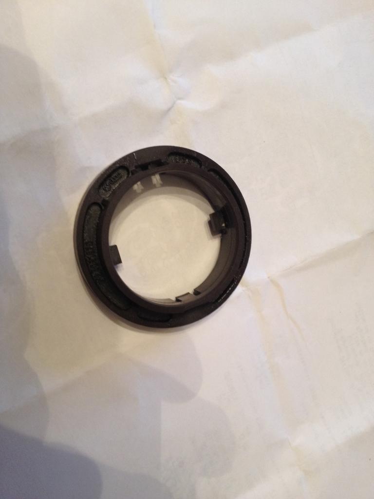
Here's the speedo ring, it has eight magnetic poles on it, going to make either a plastic or alu one and put five magnets in it, think that's where I need to be as the speedo was showing 100mph at about 60.
I'm just delighted it works, at least I can work with it now.
I'm just delighted it works, at least I can work with it now.

Last edited by boosted; 19 October 2014 at 08:01 AM.
19 October 2014, 11:56 AM
#117
Scooby Regular
iTrader: (3)
Join Date: Sep 2013
Location: Newcastle upon Tyne
Posts: 78
Likes: 0
Received 0 Likes
on
0 Posts
Nice one, I assume that you got the reed switch working with the subaru Hall sensor input then.
Does the speed sensor ring clip onto the rear output shaft of the gearbox?
Does the speed sensor ring clip onto the rear output shaft of the gearbox?
 19 October 2014, 02:11 PM
#119
Scooby Regular
Thread Starter
The sensor ring is on the front diff, driveshaft off, drive flange out and the side off the diff, oil everywhere, etc etc!
100mpg was 2k rpm in sixth, so at a guess 60mph, so five magnets would read 61.5mph, close enough (four not enough, six too many)